ORION Upgrades
Posted: Thu Dec 05, 2013 4:08 am
The ORION has worked great out of the box and required zero tweaking so far. The only complaint I could have had with the printer is that when idle, it was producing a pretty jarring fan noise. I suspected the power supply fan.
Also, I was looking for a solution to light the print area while printing, since most of my printing happens at night and normal room light doesn't give you much detail on the print - especially that crucial first few layers.... I've looked at print-head mounted lights, since I thought that was a very clean and nice solution, but didn't like the idea of cluttering up the print head.
So, here's what I ended up doing to my printer today:
Power supply wires trimmed
Removed the power supply and checked the fan - it's fine. In the process, I cut off every single non-essential wire. I opened up the power supply and cut the wires as close to the PCB board as I could to prevent any shorts. I left 1 set of GND/12V/5V wires for later. Everything else went away (MoBo connector, hard drive connectors etc.). This really cleared out the wiring space under the ORION.
40mm fan replaced & connector soldered to RAMBo
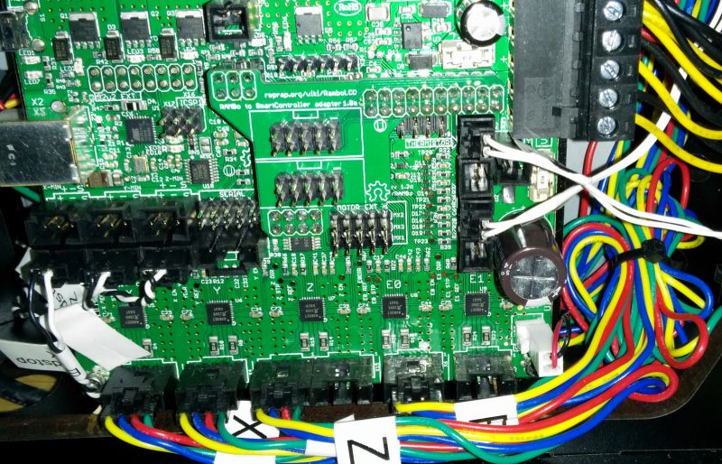
Replaced the 40mm fan behind the RAMBO board with a new one. Turns out that little fan was making awful noises, not the power supply. The fan swap *could* have been pretty straight forward, but unfortunately, the fan wires are soldered to the PCB. Not only that, they are soldered on with some solder made on Krypton or something. It was a huge pain de-soldering everything and getting the through-holes restored. I soldered in a fan connector socket.
Here's what I ended up with (see white connector, bottom right):
[img]http://www.ironcreek.net/photos/Hobby/3 ... 5324-1.jpg[/img]
I would *REALLY* recommend, that SeeMeCNC/UltiMachine make that header connector standard.
Moved power switch
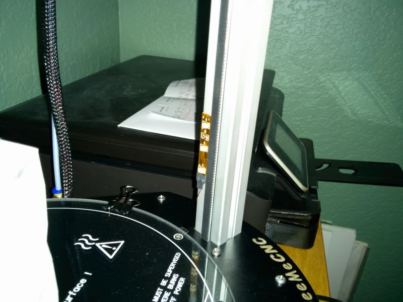
I really like how modular and easily accessible everything on the ORION is. Everything can be opened up, taken off etc. very easily. Except for the LCD panel... The ON/OFF power switch is screwed to the LCD panel plexi-glass. To be more easily accessible, I removed the switch from the panel and instead drilled a hole next to the bed and put the switch right next to the bed (see below).
Let there be light!
Then there was the light issue....
From a previous project I have reels of LED strips laying around. Since I don't want anything hanging on the print head, but need light low enough to see the first few layers, I came up with this:
[youtube]http://www.youtube.com/watch?v=23FJXeVvEZ8[/youtube]
This video also shows off the new location of the power switch (RED) and the new light switch (WHITE).
Here's a closer look at the LED strips and their location:
[img]http://www.ironcreek.net/photos/Hobby/3 ... 000001.jpg[/img]
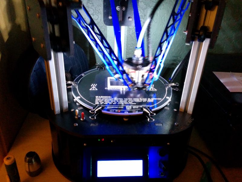
And here's a still photo with the printer in action (excuse the blur, I'm printing pretty quickly right now ):
):
[img]http://www.ironcreek.net/photos/Hobby/3 ... 005258.jpg[/img]
All this took way longer than I had anticipated, but to me, it's totally worth it.

Also, I was looking for a solution to light the print area while printing, since most of my printing happens at night and normal room light doesn't give you much detail on the print - especially that crucial first few layers.... I've looked at print-head mounted lights, since I thought that was a very clean and nice solution, but didn't like the idea of cluttering up the print head.
So, here's what I ended up doing to my printer today:
Power supply wires trimmed
Removed the power supply and checked the fan - it's fine. In the process, I cut off every single non-essential wire. I opened up the power supply and cut the wires as close to the PCB board as I could to prevent any shorts. I left 1 set of GND/12V/5V wires for later. Everything else went away (MoBo connector, hard drive connectors etc.). This really cleared out the wiring space under the ORION.
40mm fan replaced & connector soldered to RAMBo
Replaced the 40mm fan behind the RAMBO board with a new one. Turns out that little fan was making awful noises, not the power supply. The fan swap *could* have been pretty straight forward, but unfortunately, the fan wires are soldered to the PCB. Not only that, they are soldered on with some solder made on Krypton or something. It was a huge pain de-soldering everything and getting the through-holes restored. I soldered in a fan connector socket.
Here's what I ended up with (see white connector, bottom right):
[img]http://www.ironcreek.net/photos/Hobby/3 ... 5324-1.jpg[/img]
I would *REALLY* recommend, that SeeMeCNC/UltiMachine make that header connector standard.
Moved power switch
I really like how modular and easily accessible everything on the ORION is. Everything can be opened up, taken off etc. very easily. Except for the LCD panel... The ON/OFF power switch is screwed to the LCD panel plexi-glass. To be more easily accessible, I removed the switch from the panel and instead drilled a hole next to the bed and put the switch right next to the bed (see below).
Let there be light!
Then there was the light issue....
From a previous project I have reels of LED strips laying around. Since I don't want anything hanging on the print head, but need light low enough to see the first few layers, I came up with this:
[youtube]http://www.youtube.com/watch?v=23FJXeVvEZ8[/youtube]
This video also shows off the new location of the power switch (RED) and the new light switch (WHITE).
Here's a closer look at the LED strips and their location:
[img]http://www.ironcreek.net/photos/Hobby/3 ... 000001.jpg[/img]
And here's a still photo with the printer in action (excuse the blur, I'm printing pretty quickly right now
[img]http://www.ironcreek.net/photos/Hobby/3 ... 005258.jpg[/img]
All this took way longer than I had anticipated, but to me, it's totally worth it.