BondTech QR Extruder Tip #1 - Calibration

A place to talk about user-made mods and upgrades to their machines
User avatar
mhackney
ULTIMATE 3D JEDI
Posts: 5412
Joined: Mon Mar 26, 2012 4:15 pm
Location: MA, USA
Contact:

BondTech QR Extruder Tip #1 - Calibration

Post by mhackney »

The new QR extruders have been out for a few weeks now and I've been running 2 in a dual extruder setup with an E3D Cyclops switching hot end. They have worked flawlessly. Even though they come pre-assembled and Martin provides a default calibration steps/mm you'll likely find you can do a bit better by actually calibrating. This thread will be used for tips setting up and using the QRs.

Firstly, there is a BondTech forum and I would expect it to pick up soon.

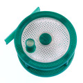
Martin has published some nice Bowden tube clips - print one for each of your extruders:

1.75 mm clip
3.00 mm clip

Here's one printed. These are nice, I now use them on all my PTC couplers.
FullSizeRender 8.jpg
These insert on the OUTPUT side. Basically, they insert between the little black plastic collar and the brass body of the PTC fitting and remove the backlash of the fitting moving up and down slightly during retracts, etc.

Calibration
The recommended default values are:

490 steps/mm for 1.75 mm version
510 steps/mm for 3.0 mm version

The following extruder calibration method is applicable to any Bowden extruder.

First, cut a ~10cm length of PTFE tubing for your machine - we'll call it the output tube. You are going to disconnect the Bowden tube and insert this short piece into the OUTPUT side of the extruder. Don't forget to remove the tube clip and then re-insert it once the short tube is installed. Make sure it is seated all the way into the QR.

With a sharp hobby knife, cut the end of your filament clean and square.

Now you can loosen the QR lever on the side (thumbscrew) and feed the filament through until the cut end is flush with the end of the short output tube. We are going to use the end of the PTFE tube as our reference point.

TIP: When using the QR lever, you loosen the thumbscrew and then depress the lever to release pressure on the filament so you can move it. I was lazy the first several time and loosened the screw enough hoping that I wouldn't have to depress the lever. Well, the screw, washer and spring fell out and behind my workbench. 30 frustrating minutes later I found them! I did this twice before I wised up! Let me save you the pain and tell you to loosen the screw and depress the lever to move the filament. Once you've done this once you will see how far to loosen. It works great.

Now snug up the QR screw - you do not have to gorilla hand this, some spring pressure is all that's needed, the dual drive cogs do the rest.

Connect to your printer with your favorite host. Issue the command:

Code: Select all

G1 E100 F1500
from the G-code input line or you could even save this in a file (with a .gcode extension) and "print it" or upload it to your SD card to print.

This simply instructs the extruder to advance 100 mm at 1500 mm/min (or 25 mm/sec). You can also use the UI controls if your host provides them (basically they all do right on the print panel, I'll leave it as an exercise to find it in S3D). Your extruder to fire up and push 100mm of filament out the bottom.

Now measure the length of the extruded filament from the cut edge of the PTFE tube to the cut end of the filament. You can use a ruler or use the depth gauge end of your calipers like this:
FullSizeRender 7.jpg
Note: it was impossible to photo this myself. In practice, the filament should be much straighter and pressed up against the end of the height gauge. But you get the idea.

I like to do 3 samples and then average them if there is much variability. Once you have the measured length, recalculate the new calibrated steps/mm like this:

calibrated steps/mm = current steps/mm * (100.00mm/measured filament length)

so for this example:

new steps/mm = 490 steps/mm * (100.00mm/98.03mm)

new steps/mm = 499.85 steps/mm

Sublime Layers - my blog on Musings and Experiments in 3D Printing Technology and Art

Start Here:
A Strategy for Successful (and Great) Prints

Strategies for Resolving Print Artifacts

The Eclectic Angler
User avatar
bvandiepenbos
Printmaster!
Posts: 927
Joined: Thu Apr 05, 2012 11:25 pm
Location: Goshen, IN
Contact:

Re: BondTech QR Extruder Tips

Post by bvandiepenbos »

Hi Michael,
Thanks for posting the detailed step-by-step calibration info and tips, it will be very helpful to many, myself included.
I have been marking filament and/or bowden tube with a sharpie and measuring with a pocket scale.
Your method is better. I am doing it that way from now on.

I have found if you want to get even more precise you need to calibrate your steps/per for each type of filament.
PLA, ABS and Flexible filaments will feed slightly different amount. Variable softness changes the effective drive diameter.
You should also feed and measure a fresh section of filament each time, if you re-feed a section that already has marks from hob teeth it can change your measurement.


Thanks for the heads up about the QR lever.
~*Brian V.

RostockMAX v2 (Stock)
MAX METAL "ShortyMAX"
MAX METAL Rostock MAX Printer Frame
NEMESIS Air Delta v1 & v2 -Aluminum delta printers
Rostock MAX "KITT" - Tri-Force Frame
GRABER i3 "Slim"
User avatar
mhackney
ULTIMATE 3D JEDI
Posts: 5412
Joined: Mon Mar 26, 2012 4:15 pm
Location: MA, USA
Contact:

Re: BondTech QR Extruder Tips

Post by mhackney »

I've measured a lot of filaments and you are correct. But, look at the difference in the 1.75 and 3.00 mm defaults (490 s/mm and 510 s/mm) - quite small for such a large filament change. What I do is use a good PLA filament that measures to 1.75mm D to calibrate. Then I compensate for the difference in diameter or squshiness (which actually affects diameter) in the slicer.

But, with the dual cogs that are a fixed distance apart, I wonder if the QR might actually be more consistent with differences in filament diameter as long as they are within a small range.

The other cool thing about the QR is I have yet to have it leave marks on my filament. I hate that with other extruders because you just know it causes problems with snagging. The QR fees smooth with no marks, pretty nice.

Sublime Layers - my blog on Musings and Experiments in 3D Printing Technology and Art

Start Here:
A Strategy for Successful (and Great) Prints

Strategies for Resolving Print Artifacts

The Eclectic Angler
User avatar
mhackney
ULTIMATE 3D JEDI
Posts: 5412
Joined: Mon Mar 26, 2012 4:15 pm
Location: MA, USA
Contact:

Tip #2 - Infeed tubes

Post by mhackney »

Here's a tip on setting up the filament infeed. The QRs have PTC couplers on the infeed side too so you can either connect a long tube over to your filament spool or do this:
FullSizeRender 10.jpg
FullSizeRender 9.jpg
This helps in several ways.
  1. it's easy to feed the filament in, you push it through the long tube from the spool to the end where you can grab it to push through the extruder and Bowden.
  2. during retracts, the top indeed tube lifts the amount of the retract so you get a visual indiction of retract.
  3. you could insert a little felt or other lint free pad (microfiber is what I use) in the space to have a filament wiping system to remove surface grunge. PLEASE DO NOT use this to add "canola oil". I will never post another tip if you do!
For the feed tube itself I use PTFE with a 3mm ID and 4mm OD. The larger bore minimizes friction and the thinner walls allow it to bend nicely from my filament spool to the extruder. I got mine at McMaster Carr.

Sublime Layers - my blog on Musings and Experiments in 3D Printing Technology and Art

Start Here:
A Strategy for Successful (and Great) Prints

Strategies for Resolving Print Artifacts

The Eclectic Angler
User avatar
Eaglezsoar
ULTIMATE 3D JEDI
Posts: 7185
Joined: Sun Apr 01, 2012 5:26 pm

Re: BondTech QR Extruder Tip #1 - Calibration

Post by Eaglezsoar »

Michael, could you show a larger picture to show how you have mounted the Bondtechs and the model number of them? (please).
“ Do Not Regret Growing Older. It is a Privilege Denied to Many. ”
User avatar
mhackney
ULTIMATE 3D JEDI
Posts: 5412
Joined: Mon Mar 26, 2012 4:15 pm
Location: MA, USA
Contact:

Re: BondTech QR Extruder Tip #1 - Calibration

Post by mhackney »

It won't help - this is a TAZ printer. The mounts are all on the BondTech site - they clamp around the neck of the geared part of the stepper. My Rostock mount is not ready yet - printing now. I'll photo when mounted. What model # are you asking about? They are simply called "QR".

cheers,
Michael

Sublime Layers - my blog on Musings and Experiments in 3D Printing Technology and Art

Start Here:
A Strategy for Successful (and Great) Prints

Strategies for Resolving Print Artifacts

The Eclectic Angler
User avatar
mhackney
ULTIMATE 3D JEDI
Posts: 5412
Joined: Mon Mar 26, 2012 4:15 pm
Location: MA, USA
Contact:

BondTechQR Rostock Max Mount

Post by mhackney »

I tried to design this to be an easy retrofit for the Rostock Max V1 and V2. I have a V1 and it literally just replaces one of the top mounted extruders in pre-existing top plate holes. It will sit closer to the top plate than the stock ezStruder but that's fine, there is still plenty of room to access the lever and feed filament.

Print with 3 shells, 3 perimeters and your choice of infill at 25%. All M3 hardware. You need two M3 threaded inserts the short size works if you have them, if not the long ones are best. Turns out that BondTech sells these on their accessories page so pick 2 up when you order your QR if you don't routinely use threaded inserts and don't need 100! You can use a regular soldering iron with a small point to install, no special installation tips needed. Note that the smaller diameter end goes in first. Another tip is to use low heat. If you go in too hot, you'll make a mess and the insert will likely be tilted and not held in well. Low heat and a nice slow insert does it.
FullSizeRender 11.jpg
I'll take some photos and list the other hardware once I have mine mounted. I'm waiting for some new QRs though and with Christmas travel coming up, it might be a few weeks.
Rostock QR Mount.stl
(1.81 MiB) Downloaded 304 times

Sublime Layers - my blog on Musings and Experiments in 3D Printing Technology and Art

Start Here:
A Strategy for Successful (and Great) Prints

Strategies for Resolving Print Artifacts

The Eclectic Angler
User avatar
Eaglezsoar
ULTIMATE 3D JEDI
Posts: 7185
Joined: Sun Apr 01, 2012 5:26 pm

Re: BondTech QR Extruder Tip #1 - Calibration

Post by Eaglezsoar »

Thanks for the STL, now I see how they are mounted.
“ Do Not Regret Growing Older. It is a Privilege Denied to Many. ”
User avatar
mhackney
ULTIMATE 3D JEDI
Posts: 5412
Joined: Mon Mar 26, 2012 4:15 pm
Location: MA, USA
Contact:

Re: BondTech QR Extruder Tip #1 - Calibration

Post by mhackney »

Screen Shot 2015-12-12 at 9.55.38 AM.png
This is a rendering of the Rostock mount for the BondTech QR. Let me know if you print one and how it turned out - especially if you have any tweaks to recommend.

Sublime Layers - my blog on Musings and Experiments in 3D Printing Technology and Art

Start Here:
A Strategy for Successful (and Great) Prints

Strategies for Resolving Print Artifacts

The Eclectic Angler
User avatar
mhackney
ULTIMATE 3D JEDI
Posts: 5412
Joined: Mon Mar 26, 2012 4:15 pm
Location: MA, USA
Contact:

Re: BondTech QR Extruder Tip #1 - Calibration

Post by mhackney »

Hey folks, it looks like the mount holes for the V1 and V2 might be different. I have a V1 and the holes in the top plate are 40mm apart. Can someone with a V2 please check the hole spacing for me? Even better, if you could print this mount to do a dry run fit to see if it will even work on a V2 would be great!

Sublime Layers - my blog on Musings and Experiments in 3D Printing Technology and Art

Start Here:
A Strategy for Successful (and Great) Prints

Strategies for Resolving Print Artifacts

The Eclectic Angler
User avatar
bvandiepenbos
Printmaster!
Posts: 927
Joined: Thu Apr 05, 2012 11:25 pm
Location: Goshen, IN
Contact:

Re: BondTech QR Extruder Tip #1 - Calibration

Post by bvandiepenbos »

Mine calibrated at 468 steps/MM with 1.75 PLA
Why so different than yours Michael?
~*Brian V.

RostockMAX v2 (Stock)
MAX METAL "ShortyMAX"
MAX METAL Rostock MAX Printer Frame
NEMESIS Air Delta v1 & v2 -Aluminum delta printers
Rostock MAX "KITT" - Tri-Force Frame
GRABER i3 "Slim"
User avatar
mhackney
ULTIMATE 3D JEDI
Posts: 5412
Joined: Mon Mar 26, 2012 4:15 pm
Location: MA, USA
Contact:

Re: BondTech QR Extruder Tip #1 - Calibration

Post by mhackney »

Odd! I don't know. I have 5 more to calibrate so well have more data soon.

Sublime Layers - my blog on Musings and Experiments in 3D Printing Technology and Art

Start Here:
A Strategy for Successful (and Great) Prints

Strategies for Resolving Print Artifacts

The Eclectic Angler
User avatar
nitewatchman
Printmaster!
Posts: 626
Joined: Thu May 01, 2014 9:51 pm
Location: Birmingham, Alabama

Re: BondTech QR Extruder Tip #1 - Calibration

Post by nitewatchman »

mhackney wrote:Hey folks, it looks like the mount holes for the V1 and V2 might be different. I have a V1 and the holes in the top plate are 40mm apart. Can someone with a V2 please check the hole spacing for me? Even better, if you could print this mount to do a dry run fit to see if it will even work on a V2 would be great!
This is a QR Mount modified for a Rostock V2. This has the mounting holes at 50mm on center.

Warning this has not been printed or tried at this point.
Attachments
Rostock Max V2 Mount -2.stl
(7.04 MiB) Downloaded 291 times
User avatar
mhackney
ULTIMATE 3D JEDI
Posts: 5412
Joined: Mon Mar 26, 2012 4:15 pm
Location: MA, USA
Contact:

Re: BondTech QR Extruder Tip #1 - Calibration

Post by mhackney »

So it's verified that V2 has 50mm spacing?

I'll update Martin so he can make a V2 version on my mount. He is planning to post the STLs for these on the bondtech web site.

Meanwhile, a comment on orientation. It is much better to orient the mount the way I have it in my original STL. The "overhang" part of the base is 45° and prints beautifully in that orientation AND you'll get nice round, clean holes for the stepper clamp. In this orientation, the stepper clamp holes will be difficult to print cleanly.

Sublime Layers - my blog on Musings and Experiments in 3D Printing Technology and Art

Start Here:
A Strategy for Successful (and Great) Prints

Strategies for Resolving Print Artifacts

The Eclectic Angler
User avatar
nitewatchman
Printmaster!
Posts: 626
Joined: Thu May 01, 2014 9:51 pm
Location: Birmingham, Alabama

Re: BondTech QR Extruder Tip #1 - Calibration

Post by nitewatchman »

mhackney wrote:So it's verified that V2 has 50mm spacing?

I'll update Martin so he can make a V2 version on my mount. He is planning to post the STLs for these on the bondtech web site.

Meanwhile, a comment on orientation. It is much better to orient the mount the way I have it in my original STL. The "overhang" part of the base is 45° and prints beautifully in that orientation AND you'll get nice round, clean holes for the stepper clamp. In this orientation, the stepper clamp holes will be difficult to print cleanly.

Clamp printed standing up. Original BondTech received with extruder was printed flat, it has a layer split through one of the clamp bolt holes. I did not want the layers running parallel to the holes. Guess a split the other way is not much better but the section is heavier.

gary
User avatar
mhackney
ULTIMATE 3D JEDI
Posts: 5412
Joined: Mon Mar 26, 2012 4:15 pm
Location: MA, USA
Contact:

Re: BondTech QR Extruder Tip #1 - Calibration

Post by mhackney »

Got it. I usually print with 4 perimeters so the holes are pretty strong. There isn't a lot of force on them in any case. I commented on your post on the google plus group, thanks.

Sublime Layers - my blog on Musings and Experiments in 3D Printing Technology and Art

Start Here:
A Strategy for Successful (and Great) Prints

Strategies for Resolving Print Artifacts

The Eclectic Angler
User avatar
mhackney
ULTIMATE 3D JEDI
Posts: 5412
Joined: Mon Mar 26, 2012 4:15 pm
Location: MA, USA
Contact:

Re: BondTech QR Extruder Tip #1 - Calibration

Post by mhackney »

@Brian - I just calibrated one of the new QRs I put on my Rostock. Came in at 458.55 exactly. Spot on 100.00 +/- .01 in 3 tests. It will take me some time to get through mounting the other 5 and calibrating but I'll keep a running tab here.

Sublime Layers - my blog on Musings and Experiments in 3D Printing Technology and Art

Start Here:
A Strategy for Successful (and Great) Prints

Strategies for Resolving Print Artifacts

The Eclectic Angler
User avatar
mhackney
ULTIMATE 3D JEDI
Posts: 5412
Joined: Mon Mar 26, 2012 4:15 pm
Location: MA, USA
Contact:

Installing the BondTech QR Extruder

Post by mhackney »

Meanwhile, here's some more info on installing. If you use my mount, you'll need two M3x18mm screws, washers and nuts to attache to the top plate.
FullSizeRender 15.jpg
FullSizeRender 13.jpg
FullSizeRender 16.jpg
I found it easier to install the mount without the extruder attached.

Now on to configuration. Firstly, if you are replacing and existing extruder and using the existing wiring, you will need to reverse the extrusion direction for the QR - it is opposite the ezStruder. This is done in config.g. Look for:

M569 P3 S0 ; Drive 3 (extruder) goes backwards

and change the S value to 1 or 0 - the opposite of what you currently have. The above is correct for my QR.

The next thing you need to do is calibrate as per time #1 in this thread. Once you have your steps/mm look for:

M92 E458.55:458.55 ; Set extruder steps per mm

and change the E value to your calculated steps/mm. I tested 3 times after calibrating to be sure and this QR came out to 458.55 steps/mm.

Don't forget to print and install two of the Bowden clips linked above. They stop any backlash from the coupler moving and they look cool!

Sublime Layers - my blog on Musings and Experiments in 3D Printing Technology and Art

Start Here:
A Strategy for Successful (and Great) Prints

Strategies for Resolving Print Artifacts

The Eclectic Angler
User avatar
bvandiepenbos
Printmaster!
Posts: 927
Joined: Thu Apr 05, 2012 11:25 pm
Location: Goshen, IN
Contact:

Re: BondTech QR Extruder Tip #1 - Calibration

Post by bvandiepenbos »

499, 468, 458 makes no sense to vary so much. Do the drive hobs vary in size?
~*Brian V.

RostockMAX v2 (Stock)
MAX METAL "ShortyMAX"
MAX METAL Rostock MAX Printer Frame
NEMESIS Air Delta v1 & v2 -Aluminum delta printers
Rostock MAX "KITT" - Tri-Force Frame
GRABER i3 "Slim"
User avatar
mhackney
ULTIMATE 3D JEDI
Posts: 5412
Joined: Mon Mar 26, 2012 4:15 pm
Location: MA, USA
Contact:

Re: BondTech QR Extruder Tip #1 - Calibration

Post by mhackney »

I posted on the plus group so maybe we'll get some info. I've looked at all 6 of my hobs under a magnifier and they look very cleanly machined and consistent.

Sublime Layers - my blog on Musings and Experiments in 3D Printing Technology and Art

Start Here:
A Strategy for Successful (and Great) Prints

Strategies for Resolving Print Artifacts

The Eclectic Angler
User avatar
mhackney
ULTIMATE 3D JEDI
Posts: 5412
Joined: Mon Mar 26, 2012 4:15 pm
Location: MA, USA
Contact:

Re: BondTech QR Extruder Tip #1 - Calibration

Post by mhackney »

Martin rigged up a cool fixture and shot a video he shared with me to test the calibration and reproducibility. Here is a screenshot of the fixture. The cord is hooked to counterweight so the filament goes both ways. This is neat because it removes all human measurement error and it puts a little tension on the filament to keep it straight.
Screen Shot 2015-12-20 at 3.19.20 PM.png
Martin measured some of his drive gears and they are all 11.35mm +/-0.02mm (measured at the top of the cobbled diameter). He is seeing 476.55 steps/mm for 1.75 PLA and 493.45 steps/mm for 3.0 PLA. He's seeing .01mm repeatability over 100mm.

I am going to create a similar fixture and test all 8 of mine. But some thoughts he passed on:

Make sure the drive gears are clear of any plastic debris.

Make sure the gear grooves are lined up perfectly. If the filament is not exactly in the valley, it can throw things off.

One thing to keep in mind is that 50 steps moves the filament .1mm. If you are not very precise and repeatable, even a .05mm variation would result in a variation of 25 steps/mm. The reason for measuring 100 mm of filament is to improve measurement and minimize errors but a little variation could creep in. I like Martin's fixture because it precisely measures the amount moved to the resolution of the calipers. I do not know how many different filaments and/or QRs he tested, I've asked for that.

Sublime Layers - my blog on Musings and Experiments in 3D Printing Technology and Art

Start Here:
A Strategy for Successful (and Great) Prints

Strategies for Resolving Print Artifacts

The Eclectic Angler
bot
Printmaster!
Posts: 993
Joined: Thu Sep 25, 2014 12:18 am
Location: Vancouver
Contact:

Re: BondTech QR Extruder Tip #1 - Calibration

Post by bot »

Love that test rig. I'm going to be mounting a new extruder system onto my effector soon so I will have to use that to calibrate it.
*not actually a robot
User avatar
mhackney
ULTIMATE 3D JEDI
Posts: 5412
Joined: Mon Mar 26, 2012 4:15 pm
Location: MA, USA
Contact:

Re: BondTech QR Extruder Tip #1 - Calibration

Post by mhackney »

Yeah, it's clever. Wish I thought of it.

From Martin: it was ABS he tested and only one extruded. He'll do more testing too b

Sublime Layers - my blog on Musings and Experiments in 3D Printing Technology and Art

Start Here:
A Strategy for Successful (and Great) Prints

Strategies for Resolving Print Artifacts

The Eclectic Angler
User avatar
Eaglezsoar
ULTIMATE 3D JEDI
Posts: 7185
Joined: Sun Apr 01, 2012 5:26 pm

Re: BondTech QR Extruder Tip #1 - Calibration

Post by Eaglezsoar »

nitewatchman wrote:
mhackney wrote:So it's verified that V2 has 50mm spacing?

I'll update Martin so he can make a V2 version on my mount. He is planning to post the STLs for these on the bondtech web site.

Meanwhile, a comment on orientation. It is much better to orient the mount the way I have it in my original STL. The "overhang" part of the base is 45° and prints beautifully in that orientation AND you'll get nice round, clean holes for the stepper clamp. In this orientation, the stepper clamp holes will be difficult to print cleanly.

Clamp printed standing up. Original BondTech received with extruder was printed flat, it has a layer split through one of the clamp bolt holes. I did not want the layers running parallel to the holes. Guess a split the other way is not much better but the section is heavier.

gary
This may seem to be a stupid question but it is not my first. Since the mount is printed in one piece, are we to cut it at the defined lines so that it can be bolted around the Bondtech QR?
User avatar
mhackney
ULTIMATE 3D JEDI
Posts: 5412
Joined: Mon Mar 26, 2012 4:15 pm
Location: MA, USA
Contact:

Re: BondTech QR Extruder Tip #1 - Calibration

Post by mhackney »

It is actually 2 pieces so there is no problem.

Sublime Layers - my blog on Musings and Experiments in 3D Printing Technology and Art

Start Here:
A Strategy for Successful (and Great) Prints

Strategies for Resolving Print Artifacts

The Eclectic Angler
Post Reply

Return to “Mods and Upgrades”