2nd Edition of the Rostock MAX Assembly Manual

Here's where you can find the official (and unofficial too) things like assembly instructions etc...
geneb
ULTIMATE 3D JEDI
Posts: 5365
Joined: Mon Oct 15, 2012 12:47 pm
Location: Graham, WA
Contact:

2nd Edition of the Rostock MAX Assembly Manual

Post by geneb »

SeeMeCNC sent me a full set of current production melamine parts this week. The plan is to revise the assembly manual using all the current parts to make sure the manual is as accurate as possible.

My intention is to completely disassemble my working machine and rebuild it using the new parts. All new photos, etc. I'll also be using the new gears and new plastic parts with the exception of the acetal bearing covers.

My plan was to get started this weekend. However, due to me forgetting sacrifice someone else's blood to the Tool Gods, I've now got a nice gash from the tip of my thumb to the base. This will of course slow things up considerably. :D

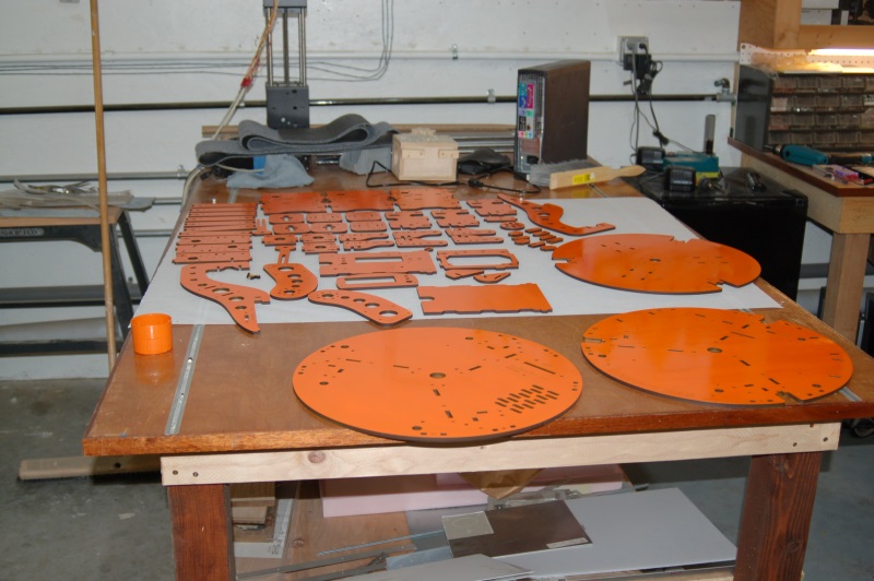
I did get the parts painted, so you'll definitely be able to spot the new photos. :D

Picture of the parts: [img]http://www.geneb.org/images/orange-max.jpg[/img]

Since there's going to be a short delay in starting work on the 2nd ed. I'd like you guys to start coming up with things that you'd like to see in the 2nd ed. that were either vague, wrong, or flat missing in the original manual.

A couple of points that I'm going to specifically cover:

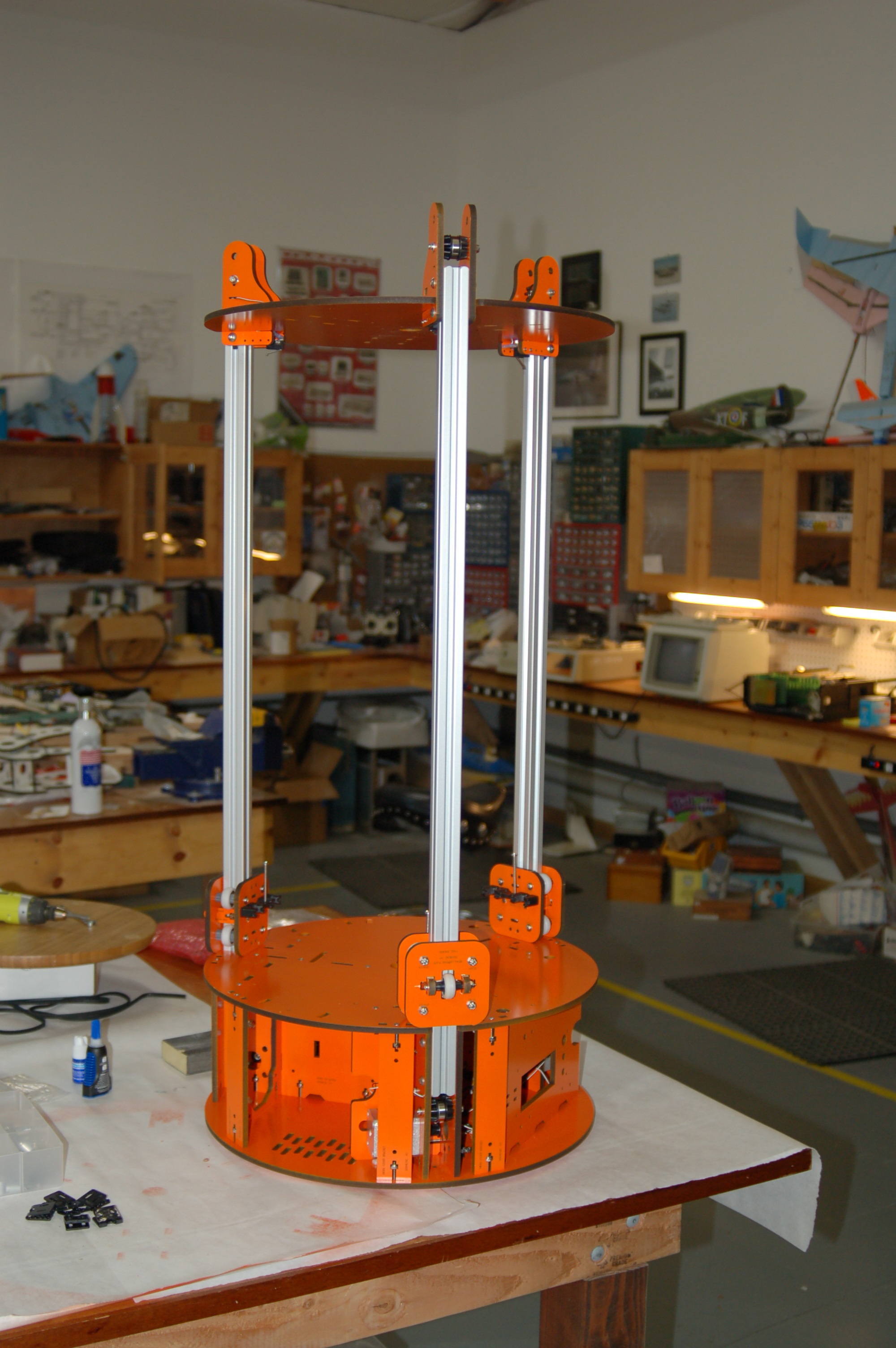
1. I'm going to show how a large square (or large speed-square) should be used to guarantee that the three towers are perfectly square to the base.

2. I'm going cut down a cheap wooden yardstick (typically they're under a buck) to use as a mechanical gauge in order to guarantee that the idler mounts are all exactly the same height.

3. The entire Phebe I section will be dropped - it's not being shipped with the kit any longer.

4. The part about threading the brackets for the plastic cover will be deleted - they're not shipping the cover any longer.

5. The current kit has mounting holes for the RAMBo on an inboard support. This is where I'll direct it be installed instead of on a door.

Where do you guys feel that the optimal position of the LCD mounting door should be?

If you have any pet peeves or corrections to make, sing out now, otherwise you've only got yourself to blame. :D

g.
Delta Power!
Defeat the Cartesian Agenda!
http://www.f15sim.com - 80-0007, The only one of its kind.
http://geneb.simpits.org - Technical and Simulator Projects
barnett
Printmaster!
Posts: 215
Joined: Tue Dec 11, 2012 5:59 am

Re: 2nd Edition of the Rostock MAX Assembly Manual

Post by barnett »

It's been a while since I looked at the manual, but here are my thoughts:
- in general, how are you going to handle all the tweaks? If I tried to write a manual, I would bog down explaining how you might add an LED here, or a second power supply there, aluminum plate, boro glass, emergency stop switch, belt tensioner, fans, etc.
- maybe there could be a section for tweaks you can print: spacers for spool holder & extruder, polygonhell's extruder cap and so on.
- white lithium grease for the u-joints?
- tips for getting your first print to stick
- calibration section (I think you already have something like this)
- for power to the heated bed, you might suggest running multiple heavier gauge wires (maybe that's already in there?)

I think seemecnc should have just sent you a whole new kit for your trouble.
User avatar
dbarrans
Printmaster!
Posts: 275
Joined: Thu Jan 03, 2013 4:14 am

Re: 2nd Edition of the Rostock MAX Assembly Manual

Post by dbarrans »

Definitely the LCD door and the RAMBo should both be between X and Y. Then, they're easier to get to from the front and won't be interfered with by an extra extruder assembly.

- dan
User avatar
cambo3d
ULTIMATE 3D JEDI
Posts: 1058
Joined: Thu Feb 07, 2013 10:03 pm
Location: Florida

Re: 2nd Edition of the Rostock MAX Assembly Manual

Post by cambo3d »

quote;" I'm going to show how a large square (or large speed-square) should be used to guarantee that the three towers are perfectly square to the base."
quote;" I'm going cut down a cheap wooden yardstick (typically they're under a buck) to use as a mechanical gauge in order to guarantee that the idler mounts are all exactly the same height."


This will only work if your base is flat and square, so might I iterate, don't assume the frame your getting is perfectly cut and accurately drawn. some things i've noticed about the seemecnc top plate is that its not symmetrical to the base. Once you've got your base flat and square. Feel free to use this technique in your manual or build, if you so choose to http://forum.seemecnc.com/viewtopic.php ... =230#p9040


There's only place to mount the lcd door and that is between the x and y towers, due to to new rambo lcd adapter wiring being to short to mount anywhere else. That's assuming your going to be installing the rambo in the xy compartment. basically you need to install the lcd in the same compartment as the rambo board.

I don't understand why seemecnc has not taken upon themselves to write a manual, they design and sell the damn thing!
User avatar
dbarrans
Printmaster!
Posts: 275
Joined: Thu Jan 03, 2013 4:14 am

Re: 2nd Edition of the Rostock MAX Assembly Manual

Post by dbarrans »

Hey, I'd be happy if SeeMeCNC would publish a change log. It would publicize their already-demonstrated commitment to improving the kit (and the design) and would probably increase parts sales too.

- dan
User avatar
Jimustanguitar
ULTIMATE 3D JEDI
Posts: 2631
Joined: Sun Mar 31, 2013 1:35 am
Location: Notre Dame area
Contact:

Re: 2nd Edition of the Rostock MAX Assembly Manual

Post by Jimustanguitar »

I agree, mount the LCD door between X and Y.

I would write the manual to install the idler bearings and motors as part of the base assembly. It is mentioned and recommended in the current version, but moving the write up to that section and adding pictures would help.

Any idea why one one the tslot supports is different than the other 2? http://i.imgur.com/KRP69GI.jpg

I would run the endstop wires through the tslots before bolting on the top. (do the wire crimps even fit through the wood the other direction?)

Include the new LCD to Rambo adapter that ships with the kits.

I would suggest that the resistor, LED, and wires for the Onyx all get tacked on to the bottom of the board. Thru-hole soldering interferes with a round build plate.

The Onyx build plate isn't included.

The Onyx mount holes don't have a "1" etched next to them anymore.

Update picture for power supply connector.

New screenshots for the Repetier firmware, Arduino, and Slic3r.
User avatar
dbarrans
Printmaster!
Posts: 275
Joined: Thu Jan 03, 2013 4:14 am

Re: 2nd Edition of the Rostock MAX Assembly Manual

Post by dbarrans »

In the configuration section, please add a warning to turn off the Repetier Host feature to move to an X offset after a print. When this is done after a G28 using Marlin firmware, it results in the printer trying to chew up its belts. Not a real good first impression.

- dan
User avatar
JohnStack
Printmaster!
Posts: 852
Joined: Thu Jan 03, 2013 7:07 pm
Location: Carlsbad, CA
Contact:

Re: 2nd Edition of the Rostock MAX Assembly Manual

Post by JohnStack »

We discussed my feedback via email, I still like the idea of getting the power supply into the base first, making sure the nylocks are there before you put the lid down, rolling nylocks into their holes (amazingly easy), and twisting the limit switch leads before threading (although, I think you have this and a couple of the others.)

Lastly, thank you for your help. Few are smart enough to build their own without your manual...
Technologist, Maker, Willing to question conventional logic
http://dropc.am/p/KhiI1a" onclick="window.open(this.href);return false;
itilguru
Plasticator
Posts: 17
Joined: Mon Apr 22, 2013 7:54 pm

Re: 2nd Edition of the Rostock MAX Assembly Manual

Post by itilguru »

JohnStack, I tried to mount the power supply first. There are two problems with it. 1) if you don't seat the t-nuts first, you're gonna have a bad time, and 2) if you make the nylon bolts anywhere near snug, good luck getting the top platform to seat at all. I had to loosen EVERYTHING to get that top on.
User avatar
Jimustanguitar
ULTIMATE 3D JEDI
Posts: 2631
Joined: Sun Mar 31, 2013 1:35 am
Location: Notre Dame area
Contact:

Re: 2nd Edition of the Rostock MAX Assembly Manual

Post by Jimustanguitar »

I would also suggest adding a line or two about setting the delta radius on a new machine. After getting your z height and all 3 axes set evenly, this is the next big geometry tweak on the list, in my book. You may also want to include a how to on printing the single wall test cube and adjusting your extruder steps per mm in the eeprom.
geneb
ULTIMATE 3D JEDI
Posts: 5365
Joined: Mon Oct 15, 2012 12:47 pm
Location: Graham, WA
Contact:

Re: 2nd Edition of the Rostock MAX Assembly Manual

Post by geneb »

Hand is all healed up so I started working on the new build yesterday. Took a couple of hours to completely disassemble Betty Goop. :)

This time around I'm going to recommend some pre-assembly steps - most notably, popping all the countersink rings in ALL the parts at the same time instead of doing it as you go.

Instead of doing the tri-supports like last time, I'm treating each one as an assembly that gets completed (stepper & belt guides) and then loosely installed in the base. This should alleviate the cramped-space issue with installing the steppers & belt guides. Thread locker is used on the drive gear grub screws as well as the stepper motor mounting screws.

Inserting the lock nuts from the lettering face of the parts makes it a lot easier as well - you're taking advantage of the laser kerf to ease the fit.

All the tri-support and circumference supports are all the same height, so having an out-of-square base won't be an issue. Looks like they got the issue they had straightened out.

I would have gotten started on Saturday, but I noticed a few poorly painted spots that needed a second coat.

g.
Delta Power!
Defeat the Cartesian Agenda!
http://www.f15sim.com - 80-0007, The only one of its kind.
http://geneb.simpits.org - Technical and Simulator Projects
Durandal
Printmaster!
Posts: 76
Joined: Thu Mar 28, 2013 9:16 pm

Re: 2nd Edition of the Rostock MAX Assembly Manual

Post by Durandal »

One thing you could also change is have the user install the end stop wires before the upper bearings and belts. I followed the instructions as written, ignoring the little blurbs saying to jump somewhere for this or that and agree with all the other recommendations so far, but I don't think that was mentioned.

Also, have a list of every tool or component not included in the kit, such as kapton, RTV, etc, this is something that the original was sorely lacking, and place it at the beginning of the instructions.

Other than that, all the wiring would be cool, just saying "yeah, now for all the rest just follow the rambo documentation" without pointing to what documentation isn't really good enough for the not technical folks, and is even frustrating an engineer like myself.
User avatar
JohnStack
Printmaster!
Posts: 852
Joined: Thu Jan 03, 2013 7:07 pm
Location: Carlsbad, CA
Contact:

Re: 2nd Edition of the Rostock MAX Assembly Manual

Post by JohnStack »

Durandal wrote:One thing you could also change is have the user install the end stop wires before the upper bearings and belts. I followed the instructions as written, ignoring the little blurbs saying to jump somewhere for this or that and agree with all the other recommendations so far, but I don't think that was mentioned.

Also, have a list of every tool or component not included in the kit, such as kapton, RTV, etc, this is something that the original was sorely lacking, and place it at the beginning of the instructions.

Other than that, all the wiring would be cool, just saying "yeah, now for all the rest just follow the rambo documentation" without pointing to what documentation isn't really good enough for the not technical folks, and is even frustrating an engineer like myself.
Good suggestions. Do the stop wires, and def do the Rambo stuff - of course you have LOADs of time! :mrgreen:
Technologist, Maker, Willing to question conventional logic
http://dropc.am/p/KhiI1a" onclick="window.open(this.href);return false;
Durandal
Printmaster!
Posts: 76
Joined: Thu Mar 28, 2013 9:16 pm

Re: 2nd Edition of the Rostock MAX Assembly Manual

Post by Durandal »

Also, the blind nuts bite into the melamine just fine, remove the instructions to bend the barbs back on the heated bed nuts.
geneb
ULTIMATE 3D JEDI
Posts: 5365
Joined: Mon Oct 15, 2012 12:47 pm
Location: Graham, WA
Contact:

Re: 2nd Edition of the Rostock MAX Assembly Manual

Post by geneb »

Durandal wrote:One thing you could also change is have the user install the end stop wires before the upper bearings and belts. I followed the instructions as written, ignoring the little blurbs saying to jump somewhere for this or that and agree with all the other recommendations so far, but I don't think that was mentioned.
Noted.
Also, have a list of every tool or component not included in the kit, such as kapton, RTV, etc, this is something that the original was sorely lacking, and place it at the beginning of the instructions.
You're kidding me right? Please tell me what you see on pages 3 and 4 of EVERY release of the PDF?
Other than that, all the wiring would be cool, just saying "yeah, now for all the rest just follow the rambo documentation" without pointing to what documentation isn't really good enough for the not technical folks, and is even frustrating an engineer like myself.
I am revising the entire document, not just selected bits and pieces. The RAMBo section will be revisited.
[I just took a peek at the manual, pages 81 & 82, and while it's not a thorough treatise on wiring the device, it's quite clear. I did make a poor choice of annotation color on Fig. 124] By looking at Fig. 124 and looking at the huge picture of the RAMBo included with the kit, an 8 year old should be able to wire that thing without any difficulty.

Note that 3D printer kits are decidedly NOT for "non-technical folks". I don't write for /r/explainlikeimfive.

g.
Delta Power!
Defeat the Cartesian Agenda!
http://www.f15sim.com - 80-0007, The only one of its kind.
http://geneb.simpits.org - Technical and Simulator Projects
JakeCShake
Printmaster!
Posts: 92
Joined: Sun Dec 16, 2012 7:57 pm
Location: Rhode Island

Re: 2nd Edition of the Rostock MAX Assembly Manual

Post by JakeCShake »

Too funny......love it :D :P :D :P
Durandal
Printmaster!
Posts: 76
Joined: Thu Mar 28, 2013 9:16 pm

Re: 2nd Edition of the Rostock MAX Assembly Manual

Post by Durandal »

geneb wrote:
Durandal wrote: Also, have a list of every tool or component not included in the kit, such as kapton, RTV, etc, this is something that the original was sorely lacking, and place it at the beginning of the instructions.
You're kidding me right? Please tell me what you see on pages 3 and 4 of EVERY release of the PDF?
Waitress, can I get an order of crow here? Yeah, I just looked at my copy of 1.17, which I swear I've read over five times, and hadn't previously seen that list. Sorry.
geneb wrote:
Durandal wrote: Other than that, all the wiring would be cool, just saying "yeah, now for all the rest just follow the rambo documentation" without pointing to what documentation isn't really good enough for the not technical folks, and is even frustrating an engineer like myself.
I am revising the entire document, not just selected bits and pieces. The RAMBo section will be revisited.
[I just took a peek at the manual, pages 81 & 82, and while it's not a thorough treatise on wiring the device, it's quite clear. I did make a poor choice of annotation color on Fig. 124] By looking at Fig. 124 and looking at the huge picture of the RAMBo included with the kit, an 8 year old should be able to wire that thing without any difficulty.

Note that 3D printer kits are decidedly NOT for "non-technical folks". I don't write for /r/explainlikeimfive.

g.
I understand you're not going in and editing pieces of the documentation, you're completely re-writing it, but inevitably the new version will look a lot like the old one, it's just how technical documents evolve. And I'm not saying that a given user shouldn't be required to perform some critical thinking, but for instance the Rambo boards come with a black and white printout of the pins for the stepper motors, and fig 124 is rather blurry, I can't make out which wires go where on the connector, looks like Green Blue Red Black going from left to right. Even if the user tracks down the color version of the Rambo pin outs, ultimachine has Red Green Yellow Blue wires, at least on the one hosted at reprap wiki. You asked for ideas on how to improve the instructions, I offered some, sorry if my ideas are beneath you and your technical skills, I just thought these particular sections might help some people who might need it.
User avatar
cambo3d
ULTIMATE 3D JEDI
Posts: 1058
Joined: Thu Feb 07, 2013 10:03 pm
Location: Florida

Re: 2nd Edition of the Rostock MAX Assembly Manual

Post by cambo3d »

gene i'd recommend doing this extra step to make setting your z height slightly easier. setting up a script for all three cal points and just clicking the script button when you need to adjust a certian axis. makes it a lil more automated and slightly simplied. just change the calibration points to what your using in your manual.

http://www.youtube.com/watch?v=XmP9JQPAlr4
ApacheXMD
Printmaster!
Posts: 186
Joined: Fri Mar 08, 2013 1:11 am

Re: 2nd Edition of the Rostock MAX Assembly Manual

Post by ApacheXMD »

I agree that Fig 124 picture could use an update and the wiring section caused me some confusion as well.

The blurriness caused me some confusion because it is not immediately apparent which pins are used for the endstop connectors. Also where the two thermistor plugs go is not obvious. The blurriness makes it hard to tell which of the four ports the two connectors need to go.
geneb
ULTIMATE 3D JEDI
Posts: 5365
Joined: Mon Oct 15, 2012 12:47 pm
Location: Graham, WA
Contact:

Re: 2nd Edition of the Rostock MAX Assembly Manual

Post by geneb »

I was aware of the calibration video - it showed up on a mailing list that I'm on. :)

With only a couple of exceptions, _all_ the pictures are being re-shot. As a result of that, all the annotations will be new and will use a higher contrast color.

Keep in mind that the original assembly and photos centered around the Indiegogo campaign machine. The large number of structural changes are what pushed me to do a second edition. Many if not all of the suggestions received since the original 1.0 manual will be included. I'm quite sure you guys will sing out if I miss something. :D

Durandal, see pages 19 and 20. Fig. 124 is a general guideline to show what connectors go where, not how to wire connectors.

BTW, cool nick. :D http://en.wikipedia.org/wiki/BLU-107_Durandal

g.
Delta Power!
Defeat the Cartesian Agenda!
http://www.f15sim.com - 80-0007, The only one of its kind.
http://geneb.simpits.org - Technical and Simulator Projects
geneb
ULTIMATE 3D JEDI
Posts: 5365
Joined: Mon Oct 15, 2012 12:47 pm
Location: Graham, WA
Contact:

Re: 2nd Edition of the Rostock MAX Assembly Manual

Post by geneb »

I finished the basic mechanical assembly on Saturday (not including installing the arms & effector platform).

Here's what it looks like:

http://www.geneb.org/images/orange-max2.jpg [It's an un-resized image]

The photo doesn't show the belts installed, but that was done as well. Up to this point I've got about 120 pictures taken. The RAMBo and LCD installation will be covered last in order to have a firm line between the mechanical and electronic assembly. I do have the new machined arms, so those will be featured.

I'm writing the 2nd ed. using LibreOffice Writer so that you won't need MS Office 2010 to make changes to the document once it's up on GitHub.
The Figure numbering has changed to be sequential within a topic section (eg. Fig. 1-23) instead of purely sequential. That makes it possible to associate them with the section they pertain to.

I'll be posting a WIP draft some time this week that'll cover the mechanical portion. When the WIP is posted and you notice that I've missed a process improvement, yell! I'll be referring to this thread as well as my own notes while I write, but things can get missed. :)

g.
Delta Power!
Defeat the Cartesian Agenda!
http://www.f15sim.com - 80-0007, The only one of its kind.
http://geneb.simpits.org - Technical and Simulator Projects
User avatar
dbarrans
Printmaster!
Posts: 275
Joined: Thu Jan 03, 2013 4:14 am

Re: 2nd Edition of the Rostock MAX Assembly Manual

Post by dbarrans »

I sure hope you like that color. :-)

- dan
geneb
ULTIMATE 3D JEDI
Posts: 5365
Joined: Mon Oct 15, 2012 12:47 pm
Location: Graham, WA
Contact:

Re: 2nd Edition of the Rostock MAX Assembly Manual

Post by geneb »

Well the original plan was to leave it white and only paint the edges orange. Time constraints precluded that (you have to clean the laser cut edges to get the paint to stick properly), so it became ALL orange. If I build a new one using my original melamine parts, it'll be blue with yellow edges (Link Simulator colors!)

g.
Delta Power!
Defeat the Cartesian Agenda!
http://www.f15sim.com - 80-0007, The only one of its kind.
http://geneb.simpits.org - Technical and Simulator Projects
barnett
Printmaster!
Posts: 215
Joined: Tue Dec 11, 2012 5:59 am

Re: 2nd Edition of the Rostock MAX Assembly Manual

Post by barnett »

I mentioned this in another post, but FYI I received a replacement stepper motor from seemecnc and the wire colors are different than those mentioned in the manual around "4 – Install the Connectors on the Stepper Motors."

If new kits have these different colored wires you might want to include that in the manual. Here's the map from old wires to new wires.

old wires ... new wires
black ........ blue
green ....... yellow
blue ......... green
red .......... red
geneb
ULTIMATE 3D JEDI
Posts: 5365
Joined: Mon Oct 15, 2012 12:47 pm
Location: Graham, WA
Contact:

Re: 2nd Edition of the Rostock MAX Assembly Manual

Post by geneb »

Thanks barnett. That matches what I got from John last week. I'm going to include both wiring color sets as they've still got stock on the older stepper motors.

g.
Delta Power!
Defeat the Cartesian Agenda!
http://www.f15sim.com - 80-0007, The only one of its kind.
http://geneb.simpits.org - Technical and Simulator Projects
Post Reply

Return to “Rostock MAX Official Docs”