Pingel's v2

Start your own build thread so others can see how it's going, and even help out!
User avatar
Pingel
Printmaster!
Posts: 56
Joined: Fri Mar 14, 2014 12:14 pm
Location: Portland, Oregon
Contact:

Pingel's v2

Post by Pingel »

Moved the thread here and added more pictures

http://imgur.com/a/DzGBh" onclick="window.open(this.href);return false;

[03APR2014] Done! here's a boring video!
https://www.youtube.com/watch?feature=p ... BzA6I4dSeg" onclick="window.open(this.href);return false;
My Mom couldn't process a 3D printer in her head so I sent her this video of it in action.

[img]http://www.reactiongifs.com/r/activate.gif[/img]


Questions!

1. Does it matter what black and yellow wires you use from the power supply to the board? [Answered]
Jimustanguitar wrote:Every yellow wire is +12v and every black wire is ground. The more the better is the general rule of thumb. You shouldn't have to do anything with red. The green one is the power switch for the ATX supply.
2. Is there an efficient way to clean the burnt smudges on the white sides of some parts? [Answered]
Jimustanguitar wrote:I had some burn spots, and windex did the trick.
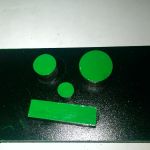
3. The flat side of the LED is the negative side, right? [Answered]
Eaglezsoar wrote:Yes, the flat side at the bottom of the led is the negative side or in this case, ground.
4. Page 231 tells me to cut off 3.5" from the 18ga wire because I have "a lot of extra 18ga wire" but... My 18ga wire doesn't even make it beyond the power supply coming from the Z axis, which I think is already a problem. Also, I seem to have miles of extra 22ga wire at the base. [Answered]
Pingel wrote:Just measured the 18ga stripped outer jacket and I had just under 7 feet total... Should have definitely measured that first... and 8 feet measured on the 22ga jacket.
Pingel wrote:I also remembered that I cut off 18" of the 18ga wire for the Onyx bed so I was probably much closer to 10 feet but still ended up short. I'm finishing up the LCD panel now then I'll see how this wiring stuff works out.
5. For the extruder steps per mm, if you extrude 10mm... is it 10mm into the hose or 10mm coming out of the hot end?

6. On the temperature of the hot end, mine constantly varies in a 10 degree window. If it's set at 228 for the print, during the whole print it will constantly go back and forth between 222 and 232. I really doubt this is normal and I have done the PID tuning a few times. Is there another test/calibration to do?

7. I tried changing the speed on the LCD of the printer and I was wondering if you slow down the speed, should you slow down flow too? Would it be better to use the feedrate speed slider in repetier-host?

8. Are either of the fan shrouds required for ABS? I tried printing the PEEK one but I can't get it clean enough to fit the fan into and ending up breaking the casing on the fan. If it's required I'll make one now, sand it down and make the fan work, I'll order a new fan here in a bit. [Answered]
Eaglezsoar wrote:You asked if any of the fan shrouds are important for ABS and although the layer fan is not normally used with ABS
the Peek fan is the most important fan on the printer and should be running when the hotend is heating and should stay
on as long as the hotend has power. Without the Peek fan, you run the risk of melting the Peek section of your hotend and
it is not a matter of if it will melt the Peek section, it is when will it melt the Peek section. You should get that peek fan running
as soon as possible even if you have to hold it in place with bubble gum, it is that important. Please get it running before you do
any other printer, I do not want you to destroy your hotend.
As a side note, the layer fan is normally used with PLA and turns on after the first layer is printed. Some use it with ABS also, but
normally is not required with ABS.
Last edited by Pingel on Fri Apr 04, 2014 1:04 pm, edited 10 times in total.
User avatar
Eaglezsoar
ULTIMATE 3D JEDI
Posts: 7185
Joined: Sun Apr 01, 2012 5:26 pm

Re: Pingel's v2

Post by Eaglezsoar »

Yes, the flat side at the bottom of the led is the negative side or in this case, ground.
User avatar
Pingel
Printmaster!
Posts: 56
Joined: Fri Mar 14, 2014 12:14 pm
Location: Portland, Oregon
Contact:

Re: Pingel's v2

Post by Pingel »

Eaglezsoar wrote:Yes, the flat side at the bottom of the led is the negative side or in this case, ground.
[img]http://www.reactiongifs.com/wp-content/ ... wesome.gif[/img]
User avatar
Pingel
Printmaster!
Posts: 56
Joined: Fri Mar 14, 2014 12:14 pm
Location: Portland, Oregon
Contact:

Re: Pingel's v2

Post by Pingel »

Added a couple more pictures to the imgur link.

I screwed up big time twice.

- I didn't notice the hole pattern on the inside cheapskate carriage plate and mounted one on backwards, I didn't notice until I tried putting it on the tower and couldn't figure out the problem. I'm glad I only had one of them backwards, if they all were backwards I would have just assumed it was a tight fit then would have had crooked cheapskates.

- I mounted the top plate one rotation off. It seems to be an easy fix but will take a bit of time redoing stuff. I'll fix that tonight.
User avatar
Eaglezsoar
ULTIMATE 3D JEDI
Posts: 7185
Joined: Sun Apr 01, 2012 5:26 pm

Re: Pingel's v2

Post by Eaglezsoar »

Nothing worse than crooked cheapskates, I hear a lot of them occupy top offices in the Government.
User avatar
Pingel
Printmaster!
Posts: 56
Joined: Fri Mar 14, 2014 12:14 pm
Location: Portland, Oregon
Contact:

Re: Pingel's v2

Post by Pingel »

Eaglezsoar wrote:Nothing worse than crooked cheapskates, I hear a lot of them occupy top offices in the Government.
[img]http://emotibot.net/pix/8120.gif[/img]
geneb
ULTIMATE 3D JEDI
Posts: 5367
Joined: Mon Oct 15, 2012 12:47 pm
Location: Graham, WA
Contact:

Re: Pingel's v2

Post by geneb »

The most recent edit to the manual makes it clear how to correctly orient the parts now.

g.
Delta Power!
Defeat the Cartesian Agenda!
http://www.f15sim.com - 80-0007, The only one of its kind.
http://geneb.simpits.org - Technical and Simulator Projects
User avatar
Pingel
Printmaster!
Posts: 56
Joined: Fri Mar 14, 2014 12:14 pm
Location: Portland, Oregon
Contact:

Re: Pingel's v2

Post by Pingel »

geneb wrote:The most recent edit to the manual makes it clear how to correctly orient the parts now.

g.

You're awesome too!

I should have noticed, it's obvious in the picture but it being obvious in text is even better.
geneb
ULTIMATE 3D JEDI
Posts: 5367
Joined: Mon Oct 15, 2012 12:47 pm
Location: Graham, WA
Contact:

Re: Pingel's v2

Post by geneb »

I really scratch my head at issues like this. I guess the photos are clear to ME and not anybody else. :)

When the new cheapskates come out, it'll be a moot point though. :D

g.
Delta Power!
Defeat the Cartesian Agenda!
http://www.f15sim.com - 80-0007, The only one of its kind.
http://geneb.simpits.org - Technical and Simulator Projects
User avatar
Pingel
Printmaster!
Posts: 56
Joined: Fri Mar 14, 2014 12:14 pm
Location: Portland, Oregon
Contact:

Re: Pingel's v2

Post by Pingel »

geneb wrote:I really scratch my head at issues like this. I guess the photos are clear to ME and not anybody else. :)
For me it's really hard to create a guide when you have a complete understanding of the purpose of the guide, if that makes sense... Most of our drafters are old school manual drafting or went through the architectural program at the community college. I'm the only one that is fluent in 3D drafting, I have done guides and a few videos for other drafters in my office and I get really frustrated when they don't understand. What I've been doing lately is after creating the guide, I sit down with our least trained drafter and run through it with him while making edits until he is able to understand everything.

I'm sure none of that is relevant of a guide to building a 3D printer but I feel your pain!
geneb
ULTIMATE 3D JEDI
Posts: 5367
Joined: Mon Oct 15, 2012 12:47 pm
Location: Graham, WA
Contact:

Re: Pingel's v2

Post by geneb »

Oh I don't know. Teaching is teaching, no matter the subject I suspect. :)

I learned pencil & vellum drafting years ago and I took to AutoCAD like a starving man after a ham sandwich. :D

g.
Delta Power!
Defeat the Cartesian Agenda!
http://www.f15sim.com - 80-0007, The only one of its kind.
http://geneb.simpits.org - Technical and Simulator Projects
User avatar
Pingel
Printmaster!
Posts: 56
Joined: Fri Mar 14, 2014 12:14 pm
Location: Portland, Oregon
Contact:

Re: Pingel's v2

Post by Pingel »

geneb wrote:Oh I don't know. Teaching is teaching, no matter the subject I suspect. :)

I learned pencil & vellum drafting years ago and I took to AutoCAD like a starving man after a ham sandwich. :D

g.

I'm impressed, we have a guy here at work that designs his own large scale R/C planes but he prefers to spend hours working on it by hand rather than on the computer using the stuff we have here in the office. I have a hard time explaining x-refs, model & paper space, blocks. He also doesn't use snaps and just places objects close to other objects, it drives me nuts and the engineers don't notice because they look at everything on paper.
geneb
ULTIMATE 3D JEDI
Posts: 5367
Joined: Mon Oct 15, 2012 12:47 pm
Location: Graham, WA
Contact:

Re: Pingel's v2

Post by geneb »

I'd lose my mind doing that. I used to be heavy into R/C about 5-6 years ago. I'd pull in a NACA airfoil, add whatever interior features needed (spars, etc), pedit the thing and then save all the ribs out as a dxf that would then be fed into another program that would nest them into a stock sheet size. From there it hit the laser cutter and I was off and going.

I've got one wing that has a laser cut "truss" spar made from two 1/16" layers of aircraft ply. It's VERY strong. It's a shame I made the wing too short and the diehedral too deep though. Max speed is about 25mph, but stall is around 23. :) It's also got an ugly, ugly tendency to snap roll at the drop of a hat. :)

g.
Delta Power!
Defeat the Cartesian Agenda!
http://www.f15sim.com - 80-0007, The only one of its kind.
http://geneb.simpits.org - Technical and Simulator Projects
User avatar
Pingel
Printmaster!
Posts: 56
Joined: Fri Mar 14, 2014 12:14 pm
Location: Portland, Oregon
Contact:

Re: Pingel's v2

Post by Pingel »

User avatar
Eaglezsoar
ULTIMATE 3D JEDI
Posts: 7185
Joined: Sun Apr 01, 2012 5:26 pm

Re: Pingel's v2

Post by Eaglezsoar »

geneb wrote:I'd lose my mind doing that. I used to be heavy into R/C about 5-6 years ago. I'd pull in a NACA airfoil, add whatever interior features needed (spars, etc), pedit the thing and then save all the ribs out as a dxf that would then be fed into another program that would nest them into a stock sheet size. From there it hit the laser cutter and I was off and going.

I've got one wing that has a laser cut "truss" spar made from two 1/16" layers of aircraft ply. It's VERY strong. It's a shame I made the wing too short and the diehedral too deep though. Max speed is about 25mph, but stall is around 23. :) It's also got an ugly, ugly tendency to snap roll at the drop of a hat. :)

g.
My diehedral was too deep once and I fell in and wasn't found for 3 days! :D
User avatar
Eaglezsoar
ULTIMATE 3D JEDI
Posts: 7185
Joined: Sun Apr 01, 2012 5:26 pm

Re: Pingel's v2

Post by Eaglezsoar »

geneb wrote:I really scratch my head at issues like this. I guess the photos are clear to ME and not anybody else. :)

When the new cheapskates come out, it'll be a moot point though. :D

g.
Do you mean these cheapskates?
New Cheapskate.jpg
geneb
ULTIMATE 3D JEDI
Posts: 5367
Joined: Mon Oct 15, 2012 12:47 pm
Location: Graham, WA
Contact:

Re: Pingel's v2

Post by geneb »

Yep!

g.
Delta Power!
Defeat the Cartesian Agenda!
http://www.f15sim.com - 80-0007, The only one of its kind.
http://geneb.simpits.org - Technical and Simulator Projects
User avatar
Prozac
Printmaster!
Posts: 132
Joined: Thu Feb 06, 2014 9:45 pm
Location: kentucky

Re: Pingel's v2

Post by Prozac »

Damn those for some reason look really good and I dont even know what the improvements maybe , or is it just Eye Candy cause Im Hungry!.
geneb
ULTIMATE 3D JEDI
Posts: 5367
Joined: Mon Oct 15, 2012 12:47 pm
Location: Graham, WA
Contact:

Re: Pingel's v2

Post by geneb »

The assembly goes from 11 parts to 2, not including the bearings & their covers. No need to adjust eccentric cams as there's a "spring" built into the part that grips the rail properly.

g.
Delta Power!
Defeat the Cartesian Agenda!
http://www.f15sim.com - 80-0007, The only one of its kind.
http://geneb.simpits.org - Technical and Simulator Projects
User avatar
Pingel
Printmaster!
Posts: 56
Joined: Fri Mar 14, 2014 12:14 pm
Location: Portland, Oregon
Contact:

Re: Pingel's v2

Post by Pingel »

Added only one more picture and a picture of a donut...
User avatar
Eaglezsoar
ULTIMATE 3D JEDI
Posts: 7185
Joined: Sun Apr 01, 2012 5:26 pm

Re: Pingel's v2

Post by Eaglezsoar »

Pingel wrote:Added only one more picture and a picture of a donut...
Please no more pictures of donuts! I can't eat them but that picture almost had me running to the store
to buy a dozen and eat them all at once. I remember how good they taste.
User avatar
Pingel
Printmaster!
Posts: 56
Joined: Fri Mar 14, 2014 12:14 pm
Location: Portland, Oregon
Contact:

Re: Pingel's v2

Post by Pingel »

Eaglezsoar wrote: Please no more pictures of donuts! I can't eat them but that picture almost had me running to the store
to buy a dozen and eat them all at once. I remember how good they taste.
My bad, at least I didn't post a picture of the 10 boxes of donuts in the break room... :D
User avatar
Pingel
Printmaster!
Posts: 56
Joined: Fri Mar 14, 2014 12:14 pm
Location: Portland, Oregon
Contact:

Re: Pingel's v2

Post by Pingel »

3 questions...

1. On page 64 & 65 you're told to put the 26ga wire with the 22ga wire in what will be the Y tower on page 70 (which I did). However, frequently later in the guide it suggests that the 26ga wire is with the 18ga wire, did I totally screw up?

2. Page 231 tells me to cut off 3.5" from the 18ga wire because I have "a lot of extra 18ga wire" but... My 18ga wire doesn't even make it beyond the power supply coming from the Z axis, which I think is already a problem. Page 231 also suggests that the 26ga wire is with the 18ga wire... I'm going to cut off 3.5" of 18ga for now then splice some more in if I need it. Also, I seem to have miles of extra 22ga wire at the base.

3. How in the world do you get the 18ga wire to work with the latching polarized connector? I forced the wires in there but couldn't get them all the way in so there is a bit of exposed copper and the silver crimping part. I'm going to have to redo it and would like to make sure to fit it right.

EDIT: I just looked over the BOM and I should have received 10 feet of both. I must have gotten shafted in the beginning and never paid attention to the length in the BOM. I guess I'll splice some on then for sure.

EDIT 2: Just measured the 18ga stripped outer jacket and I had just under 7 feet total... Should have definitely measured that first.

EDIT 3: 8 feet measured on the 22ga jacket.

EDIT 4: The latching polarized connector and 18ga wire issue (question 3) may be because I have a crappy crimping tool that I thought would work. I have a new one on the way and will report back Tuesday.
User avatar
Pingel
Printmaster!
Posts: 56
Joined: Fri Mar 14, 2014 12:14 pm
Location: Portland, Oregon
Contact:

Re: Pingel's v2

Post by Pingel »

Okay. I discovered that I had no idea what I was doing with those connectors and got everything working okay now. After watching a video I found on here I was still doing them wrong, I was sticking the wire in way too far. There are two clasps, one for the insulation and one for the strands of wire, they are so close together that I thought both the sets of clasps were for the insulation and I had the strands of copper going beyond the latch that clips into the housing.

I also remembered that I cut off 18" of the 18ga wire for the Onyx bed so I was probably much closer to 10 feet but still ended up short. I'm finishing up the LCD panel now then I'll see how this wiring stuff works out.

Also added one more picture.
User avatar
Pingel
Printmaster!
Posts: 56
Joined: Fri Mar 14, 2014 12:14 pm
Location: Portland, Oregon
Contact:

Re: Pingel's v2

Post by Pingel »

First print is done!
I'm very happy with how it came out even though it is far from perfect. After my terrible crimping and soldering skills... I was expecting to plug it in then burst into flames.
Anyone know why the outside is smooth and the inside is globby? I have a couple black spots too.
[img]http://i.imgur.com/ivipMYV.jpg[/img]
Post Reply

Return to “The Build Zone”