Interesting idea. Firstly, there won't be any twisting under normal printing conditions, there is really no force on the joints and the springs are designed to eliminate backlash (a great feature of these ball & cup joints).
But probing is a different beast! The nozzle hits pretty hard and I've seen the effector twist significantly. Perhaps there is an imperceptible twist that is harder to see. Slowing down the probe speed in increments (to make sure it actually triggers) might shed some light. The slower speed would hit with less force and maybe less twist.
mhackney's Real V3 Build Thread
Re: mhackney's Real V3 Build Thread
Sublime Layers - my blog on Musings and Experiments in 3D Printing Technology and Art
Start Here:
A Strategy for Successful (and Great) Prints
Strategies for Resolving Print Artifacts
The Eclectic Angler
-
Mac The Knife
- ULTIMATE 3D JEDI
- Posts: 1407
- Joined: Sun May 11, 2014 6:18 pm
Re: mhackney's Real V3 Build Thread
And less G-forrce, Since the probing is relying on an accelerometer to signal when the hotend touches the bed, if you slow down the approach speed, the g-force from the stop will be lower.
R-Max V2
Eris
Folger Tech FT-5 R2
Eris
Folger Tech FT-5 R2
Re: mhackney's Real V3 Build Thread
Yes, that is the balancing point. It is probably set reasonably high to minimize false triggers though.
Sublime Layers - my blog on Musings and Experiments in 3D Printing Technology and Art
Start Here:
A Strategy for Successful (and Great) Prints
Strategies for Resolving Print Artifacts
The Eclectic Angler
Re: mhackney's Real V3 Build Thread
I admit I'm a software engineer and its a long...long time since I took any structural analysis courses but here's my possibly flawed thoughts on the issue with lateral movement and the placement of the ball joints.mhackney wrote:Interesting idea. Firstly, there won't be any twisting under normal printing conditions, there is really no force on the joints and the springs are designed to eliminate backlash (a great feature of these ball & cup joints).
The arms are either pulling or pushing the effector plate around when its moving laterally across a print. Now the arms are at an angle most (maybe all of the time) so there is a downward force as well as a lateral force but I'm going to ignore that with the hope it cancels out with the build plat pushin back on it.
So in the arms pulling the effector scenario there is now a new twisting force on the effector that wasn't there when the balls were below the plate:
Re: mhackney's Real V3 Build Thread
Nice drawings. The analysis looks correct. However, many folks are getting very good results with the current configuration even if it isn't optimal. Myself included now - and I'd like to figure out what really changed!
Sublime Layers - my blog on Musings and Experiments in 3D Printing Technology and Art
Start Here:
A Strategy for Successful (and Great) Prints
Strategies for Resolving Print Artifacts
The Eclectic Angler
Re: mhackney's Real V3 Build Thread
Hi everyone, I'm baaack! I took a little break for the last week and dove into the bed leveling issue from last week. Mhackney, have you been able to resolve your issue? I've been looking at the thread and haven't seen an update.
Here's where I am:
I decided to use my dial indicator and ran through RollieRowland's delta calibration http://forum.seemecnc.com/viewtopic.php?t=8698 It took me about 4 iterations through the process but now I am within .001 at nearly all points on the bed. I printed my first part in about a week and now that it is leveled out properly it looks gorgeous!
It seems to me that the auto-calibration should probe 6 points and not just 3 and take the tower radius into consideration to fully calibrate the printer.
Re: mhackney's Real V3 Build Thread
Yes, I have but I haven't correlated the fix to an issue. It is in a post above. On tuesday I removed the FabLam from my glass, cleaned up the bed mount area and presto, the printer calibrates properly and I've been printing 10.5" diameter donuts on bare glass (PLA) with no problem. Something is moving during the probing that is causing the problem for folks. I now have 8 people cataloged with the same thinness at the X tower issue! All in the same place is very interesting.
Sublime Layers - my blog on Musings and Experiments in 3D Printing Technology and Art
Start Here:
A Strategy for Successful (and Great) Prints
Strategies for Resolving Print Artifacts
The Eclectic Angler
OctoPrint and Raspberry Pi update
I've been using OctoPrint for a solid 2 weeks now. Finally mounted my RPi in the top powered from the RAMBo (thanks JJ for the parts). I've added some plugins and custom controls to fit my work flow. So, after a good couple of weeks I can make the following observations:
Printing untethered from USB over Wifi is fantastic. Very close to the Duet web interface experience.
The RaspberrPi USB connection is a lot less problematic since it is dedicated to the printer. No stutters, lockups, unexpected pauses. The RAMBo can do its thing without a hitch.
Installation was really simple and a great upgrade if you haven't done it. I enabled support for Cura so if I want to do a quick slice and print I can. I also added the Custom Control Editor and EEPROM Repetier Editor plugins. The EEPROM editor lets you view and change EEPROM settings from the web interface. The Custom Control Editor lets you add custom controls.
Here is the YAML to duplicate this (or you can use the Custom Editor to add your own). You also have to put the v3probing.gcode file in ~/.octoprint/scripts/gcode/custom/ on your raspberrypi.
CAREFUL! YAML is space sensitive, mess a space/indent up and it will cause all sorts of havoc.
Printing untethered from USB over Wifi is fantastic. Very close to the Duet web interface experience.
The RaspberrPi USB connection is a lot less problematic since it is dedicated to the printer. No stutters, lockups, unexpected pauses. The RAMBo can do its thing without a hitch.
Installation was really simple and a great upgrade if you haven't done it. I enabled support for Cura so if I want to do a quick slice and print I can. I also added the Custom Control Editor and EEPROM Repetier Editor plugins. The EEPROM editor lets you view and change EEPROM settings from the web interface. The Custom Control Editor lets you add custom controls.
Code: Select all
controls:
- children:
  - command: M106 S%(speed)s
    input:
    - default: 255
      name: Speed (0-255)
      parameter: speed
      slider:
        max: 255
        min: 0
    name: Enable Fan
  - command: M107
    name: Disable Fan
  layout: horizontal
  name: Fan
- children:
  - confirm: About to calibrate
    name: Auto Calibrate
    script: custom/v3Probing.gcode
    width: '2'
  - name: Set Z Height
    script: custom/setZ.gcode
    width: '2'
  - command: G28 G0 F6000 X-116.910 Y-67.500 Z10
    name: X Tower Probe Point
    width: '2'
  - command: G28 G0 F6000 X116.910 Y-67.500 Z10
    name: Y Tower Probe Point
    width: '2'
  - command: G28 G0 F6000 X0.000 Y135.000 Z10
    name: Z Tower Probe Point
    width: '2'
  - command: G28 G0 F6000 X0 Y0 Z10
    name: Center Probe Point
    width: '2'
  layout: horizontal_grid
  name: Probing
- children:
  - command: G91 G0 Z.01
    name: .01 Up
  - command: G91 G0 Z-.01
    name: .01 Down
  layout: horizontal
name: MovementSublime Layers - my blog on Musings and Experiments in 3D Printing Technology and Art
Start Here:
A Strategy for Successful (and Great) Prints
Strategies for Resolving Print Artifacts
The Eclectic Angler
Tools of the Trade...
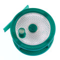
A 2" x 5" piece of leather. I use this before every print to polish the tip of the nozzle. The back side is suede-like and I'll use that to remove blobs of melted filament. Then a couple of quick swipes against the smooth side, and the nozzle is nicely polished. This minimizes filament sticking to it, which minimizes stringing and bad top surface finish. I wrote more about this on my SublimeLayers blog.
A SeeMeCNC spatula (I have 5 of them so one is almost always near by) to remove parts and clean the bed surface. I've modified mine, I bevel one side of the rounded edge so it can easily insert under the base of a print. The spatula is about .7mm thick, so what is that going to do to a print with .2mm layers? Exactly, smash it. So bevel one use with 600 grit sandpaper. I ALWAYS bevel the face that the eye logo is on, that way when I pick the spatula up, I just make sure the eyes are looking at me and that insures the bevel is in the correct orientation to do its job! I use the long edge to scrape off stuck filament from my PEI surfaces.
A pair of "normally closed" tweezers. I use these to snip blobs of filament from the nozzle tip. Even as a print starts and the nozzle descends to that magical X=Y=Z=0 spot on the bed, sometimes the flexing of the Bowden will force a little ooze out. So, tweezers at the ready, I simple squeeze them to open, grab the nozzle tip and let them close under their own power. It takes 32 seconds of practice to master this.
A 6" x 2" x 1" aluminum block. Just because! Actually, I use it for a couple of things. Some of my thin fly fishing reel parts come off the bed a little soft. I press them against this block to simultaneously flatten that surface and cool it off. I also use this thing like a happier to tap the back of my spatula for parts that are "aggressively" stuck to my bed. I intend to cut the wooden handle off square so I'm not hitting the point. There are other uses for this block, yes many other uses...
A sharp (quality) pair of wire cutters. I use these to snip filament in preparation for feeding through the extruder.
Sublime Layers - my blog on Musings and Experiments in 3D Printing Technology and Art
Start Here:
A Strategy for Successful (and Great) Prints
Strategies for Resolving Print Artifacts
The Eclectic Angler
Re: mhackney's Real V3 Build Thread
For those wanting to use the above yaml snippet and will be inserting/overwriting the control section of the Octoprint config.yaml file in the .octoprint folder. I recommend making a backup of the file before playing with it...
Re: mhackney's Real V3 Build Thread
+1 always a good idea! YAML is persnickety!
Sublime Layers - my blog on Musings and Experiments in 3D Printing Technology and Art
Start Here:
A Strategy for Successful (and Great) Prints
Strategies for Resolving Print Artifacts
The Eclectic Angler
Re: Tools of the Trade...
While I have good wire cutters, I've actually been using cat nail trimmers for that purpose. The enclosed style that shears like a cigar cutter. Gives a very good cut.mhackney wrote:...
A sharp (quality) pair of wire cutters. I use these to snip filament in preparation for feeding through the extruder.
Left over from decades of being owned by cats, before I outlived them all.
Re: mhackney's Real V3 Build Thread
I am thinking that the Octoprint custom Control screen - Movement section needs a home button/command. Would G28 be appropriate?
Re: mhackney's Real V3 Build Thread
Yes, but there is already a home button under the Z buttons. But you could easily add a button to movement with G28.
Sublime Layers - my blog on Musings and Experiments in 3D Printing Technology and Art
Start Here:
A Strategy for Successful (and Great) Prints
Strategies for Resolving Print Artifacts
The Eclectic Angler
Re: mhackney's Real V3 Build Thread
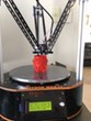
A big print
Stock V3, 0.7mm nozzle, black and natural SeeMeCNC PLA filament. .35mm layers, 2 perimeters, "Vase" setting in KISS. 195°C with 60°C bed on bare glass. 250mm/10" tall. It glows in the light.
Sublime Layers - my blog on Musings and Experiments in 3D Printing Technology and Art
Start Here:
A Strategy for Successful (and Great) Prints
Strategies for Resolving Print Artifacts
The Eclectic Angler
Re: mhackney's Real V3 Build Thread
Any chance you could post the code for your setz.gcode referred to you in custom controls?
Thanks, setz.gcode seems to overwhelm the search engine for some reason.
-Dwight
Thanks, setz.gcode seems to overwhelm the search engine for some reason.
-Dwight
Re: mhackney's Real V3 Build Thread
Yes. When I get home tomorrow night.
Sublime Layers - my blog on Musings and Experiments in 3D Printing Technology and Art
Start Here:
A Strategy for Successful (and Great) Prints
Strategies for Resolving Print Artifacts
The Eclectic Angler
Re: mhackney's Real V3 Build Thread
Just a note for the thread, it appears that the connector needed for the fan mod is Molex part #39533-2002. I will be ordering a 5 pack from Amazon tonight if I don't hear screaming that I am all wet 
http://www.mouser.com/ds/2/276/03953320 ... 141991.pdf
http://www.mouser.com/ds/2/276/03953320 ... 141991.pdf
Re: OctoPrint and Raspberry Pi update
Would you mind telling me which places on the rambo the power wires are connected to? Step 12 in the instructions does not show the connections from the rpi power to the rambo....mhackney wrote:I've been using OctoPrint for a solid 2 weeks now. Finally mounted my RPi in the top powered from the RAMBo (thanks JJ for the parts). I've added some plugins and custom controls to fit my work flow. So, after a good couple of weeks I can make the following observations:
Not sure if I am going to do it yet, just looking so far
Bob
Rostock Max V2, Ball Cup Arms, New Carriages, HE280, Dampers, PSU Breathing, Simplify 3D, GeckoTek3D, Raspberry Pi3. Duet soon... Kossel Mini still under construction.
Delta's are the way!
Rostock Max V2, Ball Cup Arms, New Carriages, HE280, Dampers, PSU Breathing, Simplify 3D, GeckoTek3D, Raspberry Pi3. Duet soon... Kossel Mini still under construction.
Delta's are the way!
Re: mhackney's Real V3 Build Thread
These work for certain: https://www.amazon.com/gp/product/B00GW ... UTF8&psc=1morgandc wrote:Just a note for the thread, it appears that the connector needed for the fan mod is Molex part #39533-2002. I will be ordering a 5 pack from Amazon tonight if I don't hear screaming that I am all wet
http://www.mouser.com/ds/2/276/03953320 ... 141991.pdf
Re: mhackney's Real V3 Build Thread
There should be several extra of these in the RAMBo electronics box. That's where I got mine. Pins too.
Sublime Layers - my blog on Musings and Experiments in 3D Printing Technology and Art
Start Here:
A Strategy for Successful (and Great) Prints
Strategies for Resolving Print Artifacts
The Eclectic Angler
Re: mhackney's Real V3 Build Thread
Unfortunately, I had lots of pins and other things leftover, but none of those. I have been through the box several times I have ordered some via amazon, should be here in a few days. Amazing how I want to leave the printer on more now that it runs the Rasberry Pi as well, now it is too loud...
Re: mhackney's Real V3 Build Thread
 setZ.gcode.txt
- (137 Bytes) Downloaded 549 times
Sublime Layers - my blog on Musings and Experiments in 3D Printing Technology and Art
Start Here:
A Strategy for Successful (and Great) Prints
Strategies for Resolving Print Artifacts
The Eclectic Angler
Checking your towers...
Find a 2' builder's square and a 12" precision metal ruler and do this:
First use the ruler to test the flatness of the glass. You can do this cold and hot to eliminate warping at temperature as a culprit.
Next, attach your bed as you normally would and then verify that all 3 towers are perpendicular like this:
[img]http://forum.seemecnc.com/download/file ... &mode=view[/img]
(click on this photo and it will be shown in the correct orientation!)
The short square arm should pass though the center of the build plate as shown. Press the short arm against the glass and then push it up to the tower. It should have no perceptible gap top to bottom. Let us know what you find.
This tests for tower lean but not sideways lean. Once you have the lean adjusted you can carefully measure edge-to-edge of a pair of towers at the top and bottom all the way around. If you are unlucky this might not tell you anything and all 3 towers could be leaning sideways the same amount. That is unlikely so you will probably find a suspect tower or two if that's the case. Fix them if so.
Many people do not verify that their towers are indeed perpendicular and not leaning and just assume all is ok. A 5 minute check will rule this out. You might be surprised how far off it is. It is easy to fix by loosening a few screws, pushing and pulling into alignment and then tightening everything up.
Sublime Layers - my blog on Musings and Experiments in 3D Printing Technology and Art
Start Here:
A Strategy for Successful (and Great) Prints
Strategies for Resolving Print Artifacts
The Eclectic Angler