My beta DropLit kit came in today! There are no manuals or instructions so I have to approach this like a puzzle! First, figure out the stuff I know and then fill in the blanks. A couple of good resources:
The DropLit GitHub - CNC files, photos, etc.
Some photos I grabbed from the SeeMeCNC site.
Here's the box:
[img]http://mhackney.zenfolio.com/img/s6/v14 ... 0964-3.jpg[/img]
and everything in it:
[img]http://mhackney.zenfolio.com/img/s10/v1 ... 5582-3.jpg[/img]
You get that nice familiar smell of laser cut melamine! Here are the melamine parts. First operation is to remove the protective film form both sides.
[img]http://mhackney.zenfolio.com/img/s6/v13 ... 3481-3.jpg[/img]
I then used the Rev 3 DXF files to identify the parts. I put a strip of masking tape on them and marked the name. While I was at it I kept all similar parts together - the door, frame, power supply mount, etc. This helped organize things and turned the daunting big pile of parts into several less daunting smaller piles!
mhackney's Beta DropLit build
mhackney's Beta DropLit build
Sublime Layers - my blog on Musings and Experiments in 3D Printing Technology and Art
Start Here:
A Strategy for Successful (and Great) Prints
Strategies for Resolving Print Artifacts
The Eclectic Angler
The front door...
As I looked over the parts I figured I'd start with the front door! That would get me familiar with the hardware and remove a few parts from the pile. Here's one of the cover sides (side A - 78721) attached to the front cover (78723) with nuts and screws. The construction is exactly like a Rosock Max - T-slots for lock nuts to slide into and tabs and slots to locate the parts. Note that the sides are different, the left side has holes to mount the hinges.
[img]http://mhackney.zenfolio.com/img/s6/v13 ... 8670-3.jpg[/img]
The front door has a piece of blue acrylic. It fits into smaller tabs on the side pieces. I guessed that I have to insert the acrylic tab into the side piece slots before tightening things down. Here you can see the tabs and slots:
[img]http://mhackney.zenfolio.com/img/s5/v11 ... 8869-3.jpg[/img]
Now I installed the other side (78721 B) and the cover name plate (78722) - which has the SeeMeCNC inscription:
[img]http://mhackney.zenfolio.com/img/s6/v14 ... 3106-3.jpg[/img]
Here's an inside-out view:
[img]http://mhackney.zenfolio.com/img/s6/v14 ... 1503-3.jpg[/img]
Now the door unit can be put aside so the acrylic does't get scratched.
Sublime Layers - my blog on Musings and Experiments in 3D Printing Technology and Art
Start Here:
A Strategy for Successful (and Great) Prints
Strategies for Resolving Print Artifacts
The Eclectic Angler
DropLit Cabinet
Next I turned my attention to the cabinet. This one was a little tricker since some of the pieces are not symmetric. I needed to figure out how the parts aligned so I did a dry mock up and used the power supply and aluminum extrusion ("Z" tower") to help visualize how things go together. It was clear that I should start with one of the cabinet sides and attach the cross pieces (bulkheads) to one side then attach the other side. Here's a dry run:
======================== EDIT ========================
I discovered later that the top piece - the stepper motor mount - needs to have the square slot opening facing to the front like this:
[img]http://mhackney.zenfolio.com/img/s6/v14 ... 6518-2.jpg[/img]
==================== END EDIT ========================
[img]http://mhackney.zenfolio.com/img/s7/v16 ... 2448-3.jpg[/img]
The sides themselves are different - one has slots for the USB cable and on-off switch. The other has holes for the hinges for the front door. The photos on the SeeMeCNC site show the left side having both the connector slots and the hinges but my parts are different! I put the hinges on the left like the SeeMeCNC photos but this puts the switch and cable connection on the right. Here's the right side with the switch and USB holes:
[img]http://mhackney.zenfolio.com/img/s12/v1 ... 8787-3.jpg[/img]
One tricky thing to figure out was the base piece. It has an off-center hole. I mocked up the base assembly with the poser supply to help figure it out:
[img]http://mhackney.zenfolio.com/img/s12/v1 ... 6778-3.jpg[/img]
Then when you take the power supply out you see how the hole should align:
[img]http://mhackney.zenfolio.com/img/s8/v83 ... 3331-3.jpg[/img]
it provides ventilation for the power supply's fan! The DropLit has 4 plastic feet that raise it off the table so that provides a path for the air.
Notice the vertical piece with the slots in it in the photo above. If you look at the SeeMeCNC photos you'll see what that is the mirror base mounting plate (78732):
[img]http://forum.seemecnc.com/download/file ... &mode=view[/img]
Now that I figured out how things lined up, I assembled the pieces to the left cabinet side.
EDIT: note that the stepper motor mount is not correct - the square slot opening needs to face front - see EDIT and photo above.
[img]http://mhackney.zenfolio.com/img/s12/v1 ... 9658-3.jpg[/img]
Note the cross brace on top - that is the stepper motor mount. The stepper will be on the right side - you can see the round hole and 4 screw holes to mount the stepper on the right of the brace. I attached the stepper motor mount (78715), the dish base (78718) , the mirror base mounting plate (78732), and the PSU base plate (78734) to the left base side (78712) )(but note that the sides are actually different although the DXF file shows 2 of the same part).
Once that was complete I installed the base (78711), note it's orientation with the wide leaf projecting to the left:
[img]http://mhackney.zenfolio.com/img/s5/v13 ... 1594-3.jpg[/img]
Then I installed the tower base (78719), it sits above dish base.
[img]http://mhackney.zenfolio.com/img/s5/v12 ... 4957-3.jpg[/img]
Sublime Layers - my blog on Musings and Experiments in 3D Printing Technology and Art
Start Here:
A Strategy for Successful (and Great) Prints
Strategies for Resolving Print Artifacts
The Eclectic Angler
DropLet Cabinet part 2
With the basic cabinet assembled, I attached the PSU mount (78733) (it is in the back of the printer). Note the orientation of the opening - it is not symmetrical and needs to be installed like this:
[img]http://mhackney.zenfolio.com/img/s7/v16 ... 2188-3.jpg[/img]
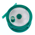
Now I attached the feet. Here are the parts:
[img]http://mhackney.zenfolio.com/img/s6/v14 ... 2369-3.jpg[/img]
The black cup attaches with a screw and nut from underneath:
[img]http://mhackney.zenfolio.com/img/s7/v16 ... 9906-3.jpg[/img]
and the feet snap on:
[img]http://mhackney.zenfolio.com/img/s7/v16 ... 6818-3.jpg[/img]
That is the basic cabinet. I dry fit the door and lower panel and top piece just to see what it will look like:
[img]http://mhackney.zenfolio.com/img/s12/v1 ... 2940-3.jpg[/img]
[img]http://mhackney.zenfolio.com/img/s7/v16 ... 0471-3.jpg[/img]
[img]http://mhackney.zenfolio.com/img/s12/v1 ... 8185-3.jpg[/img]
With
[img]http://mhackney.zenfolio.com/img/s7/v16 ... 2188-3.jpg[/img]
Now I attached the feet. Here are the parts:
[img]http://mhackney.zenfolio.com/img/s6/v14 ... 2369-3.jpg[/img]
The black cup attaches with a screw and nut from underneath:
[img]http://mhackney.zenfolio.com/img/s7/v16 ... 9906-3.jpg[/img]
and the feet snap on:
[img]http://mhackney.zenfolio.com/img/s7/v16 ... 6818-3.jpg[/img]
That is the basic cabinet. I dry fit the door and lower panel and top piece just to see what it will look like:
[img]http://mhackney.zenfolio.com/img/s12/v1 ... 2940-3.jpg[/img]
[img]http://mhackney.zenfolio.com/img/s7/v16 ... 0471-3.jpg[/img]
[img]http://mhackney.zenfolio.com/img/s12/v1 ... 8185-3.jpg[/img]
With
Sublime Layers - my blog on Musings and Experiments in 3D Printing Technology and Art
Start Here:
A Strategy for Successful (and Great) Prints
Strategies for Resolving Print Artifacts
The Eclectic Angler
Fitting out the guts
Now I turned my attention to the Z tower and mounting.
NOTE: the threaded rod for the Z axis screw is INSIDE the aluminum extrusion.
I dry fit the extrusion and discovered that I assembled the stepper motor mount incorrectly:
Opps!
[img]http://mhackney.zenfolio.com/img/s7/v15 ... 9207-3.jpg[/img]
Luckily, it was an easy fix and didn't require disassembling anything other than the motor mount. Here's how it should go:
[img]http://mhackney.zenfolio.com/img/s6/v14 ... 6518-3.jpg[/img]
At this point, the structure is complete and without the top, front, door and back, it should be easy to install the mechanics and electronics inside.
Sublime Layers - my blog on Musings and Experiments in 3D Printing Technology and Art
Start Here:
A Strategy for Successful (and Great) Prints
Strategies for Resolving Print Artifacts
The Eclectic Angler
Z tower assembly
Attach one of the T-slot mounts (78717) to the motor mount:
[img]http://mhackney.zenfolio.com/img/s7/v15 ... 7721-3.jpg[/img]
Then insert the limit switch mount (78742) with the "L" facing left:
[img]http://mhackney.zenfolio.com/img/s12/v1 ... 6492-3.jpg[/img]
Now wiggle the second T-slot mount into place and attach both T-slot mounts to the stepper motor mount plate with screws from below.
[img]http://mhackney.zenfolio.com/img/s5/v11 ... 4107-3.jpg[/img]
Next up is installing the T-slot nuts. Note that these must be assembled with the raised area AWAY from the screw head like this:
[img]http://mhackney.zenfolio.com/img/s12/v1 ... 5444-3.jpg[/img]
Install two of these on each T-Slot mount with the socket head screws - there are 6 each of the nuts and screws:
[img]http://mhackney.zenfolio.com/img/s5/v13 ... 2931-3.jpg[/img]
Then you can align the nuts so they are vertical and c*a*r*e*f*u*l*l*y slide the aluminum extrusion down from the top, making sure the T-slot nuts slide into the slots of the extrusion:
[img]http://mhackney.zenfolio.com/img/s10/v1 ... 3527-3.jpg[/img]
Push the extrusion down to about 2" above the tower base.
Now assemble two bottom T-slot mounts (78727) with one T-nut and screw each:
[img]http://mhackney.zenfolio.com/img/s12/v1 ... 6612-3.jpg[/img]
UPDATE - note the mounts go BETWEEN the plates like this:
Slide the T-nut onto the extrusion - one on each side, then push the extrusion down into the square hole in the tower base - I inserted mine about 1/4":
[img]http://mhackney.zenfolio.com/img/s2/v1/p546337533-3.jpg[/img]
EDIT: I later discovered that you need at least 1/4" between the top of the extrusion and the cabinet top to have clearance to route the stepper wires down the center of the extrusion. Turns out that inserting the extrusion about 1/4" into the tower base is just right!
I tightened up the T-nuts at this point. I may have to undo this later, I don't know yet! Conveniently, SeeMeCNC cut access holes for an Allen wrench to make it easier to tighten the T-nuts:
[img]http://mhackney.zenfolio.com/img/s5/v13 ... 8691-3.jpg[/img]
Sublime Layers - my blog on Musings and Experiments in 3D Printing Technology and Art
Start Here:
A Strategy for Successful (and Great) Prints
Strategies for Resolving Print Artifacts
The Eclectic Angler
-
Kevinvandeusen
- Printmaster!
- Posts: 123
- Joined: Wed Mar 05, 2014 9:53 pm
- Location: Cooley Springs,SC
Re: mhackney's Beta DropLet build
Great start! When I get home from Seattle, I can use this post to cheat a little! I will add my observations too.
Distributor of SeeMeCNC in South Carolina
-
Eaglezsoar

- ULTIMATE 3D JEDI
- Posts: 7159
- Joined: Sun Apr 01, 2012 5:26 pm
Re: mhackney's Beta DropLet build
Very nice writeup!
Re: mhackney's Beta DropLet build
"ain't done yet" Eagle! Now for the hard part!
One thing, I am working on the carriage now. I really don't know why they designed it with 4 bearings up front and 2 in the back, 3 points of contact with two on one side and an adjustable third on the other is more than adequate and less troublesome to adjust and maintain. I am seriously thinking about modding mine at this point with 3 points of contact.
cheers,
Michael
Sublime Layers - my blog on Musings and Experiments in 3D Printing Technology and Art
Start Here:
A Strategy for Successful (and Great) Prints
Strategies for Resolving Print Artifacts
The Eclectic Angler
Stepper and some electronics installation
I'm at the phase now where I look at the remaining parts and wonder "where do those go?"! I'll just keep moving forward with what I know and hopeful everything will fall into place.
First up, be very careful with this pink bubble wrapped package - it is the mirror!
[img]http://mhackney.zenfolio.com/img/s7/v16 ... 5849-3.jpg[/img]
The stepper is prewired with a connector. I noticed on one of the SeeMeCNC photos that the stepper wires run down the middle of the extrusion. So, that means that the column MUST sit below the top by at least 1/4" or so to allow room for the wiring. I'll make a note in the previous post.
Here is the connector, you must remove the wires so you can pass them down the extrusion. I used the tip of an X-acto knife to press on the little metal clip. This photo will help you remember the wire color ordering!
[img]http://mhackney.zenfolio.com/img/s5/v11 ... 8466-3.jpg[/img]
Here's the connector removed:
[img]http://mhackney.zenfolio.com/img/s6/v13 ... 4863-3.jpg[/img]
Position the stepper with the wires running out the back. Then pass them through the slot on the T-slot plate. I passed the wires one at a time. First, straighten out the wires and then push them in carefully. Once they protrude, just leave an inch or so sticking out. That way, when you get to the last wire - which might bind a little as it goes in - you can pull the wires already in place and they will help carry the last wire along! Clever little trick that works well. Here's what it looks like:
[img]http://mhackney.zenfolio.com/img/s10/v1 ... 9209-3.jpg[/img]
And made neat and nice:
[img]http://mhackney.zenfolio.com/img/s6/v13 ... 6116-3.jpg[/img]
Now I turned my attention to the coupler for the screw to stepper motor. Here are the parts:
[img]http://mhackney.zenfolio.com/img/s7/v15 ... 7760-3.jpg[/img]
Make sure to align one of the set screws with the flat on the stepper shaft.
[img]http://mhackney.zenfolio.com/img/s5/v11 ... 6780-3.jpg[/img]
Next up, the control board. It is a simple Arduino Uno with a gShield v5b.
[img]http://mhackney.zenfolio.com/img/s1/v56/p28629272-3.jpg[/img]
The photo shows the proper orientation for attaching the shield to the Arduino. Here's a side view on how they line up:
[img]http://mhackney.zenfolio.com/img/s6/v13 ... 3925-3.jpg[/img]
There are holes on the base (78711) that obviously line up with the mounting holes on the Arduino. But I didn't find any hardware to mount it that seemed logical. I was expecting 4 T-nuts and screws or perhaps regular nuts and screws. There are 4 white plastic standoffs - the same as the ones with the Rostock Max for mounting the RAMBo - but I don't know what screws to use yet. So I'll move on. It also isn't obvious where the stepper wires route through the cabinet. I'm sure it will become more apparent when I focus more attention on it.
NOTE: it also turns out that you need to mount the power supply before the Arduino, otherwise it won't slide in.
Finally I installed the switch on the side of the cabinet.
[img]http://mhackney.zenfolio.com/img/s6/v14 ... 9277-3.jpg[/img]
Sublime Layers - my blog on Musings and Experiments in 3D Printing Technology and Art
Start Here:
A Strategy for Successful (and Great) Prints
Strategies for Resolving Print Artifacts
The Eclectic Angler
Re: mhackney's Beta DropLet build
yer doing good, one thing I shoulda said before people got kits... you really shoulda mounted the electronics to the platform the projector sits on (the big one) before assembly, because the screw will be a royal pain to get to in order to mount the electronics... and for the bearings, I actually only use 4.. two front two back, seems to work fine, I'm starting to get great prints..
also, the endstop routes through the extrusion, the motor has a hole along the side for the wires, and zip tie holes to keep the wires along the side of the cabinet. (the side wire access hole is ran all the way down the right side of the machine) then at the bottom area there are zip tie holes for the endstop on the left and for the motor on the right, to bring the wires around the mirror and keep the wires all on the sides of the machine.
If you want any pics of mine, just let me know what parts of the machine you want a pic of and I'll post it..
Guanu
Re: mhackney's Beta DropLet build
Hey thanks. I also used 4 bearings as you did.
On the Arduino mounting, I had to text John at the show this morning to ask about it! My platform does not have holes lined up with the Arduino to mount it so the USB port is aligned with the hole in the side piece. I had to remove the platform and drill holes. While I was at it, I mounted the Arduino before reassembling. I'll show photos and document this in the next post.
Ah, I see the small holes down the right side. So the photo on the website with the stepper wires down the extrusion must be an earlier version. I'll reroute mine down the side. Then the wires should be the right length, I was going to have to extend them.
I also confirmed with John that the vats were not shipped with the kit. I also think there is a vat holder - it has a 100mm round hole for the vat - cut in melamine that I don't have either. But there is enough do for now.
Sublime Layers - my blog on Musings and Experiments in 3D Printing Technology and Art
Start Here:
A Strategy for Successful (and Great) Prints
Strategies for Resolving Print Artifacts
The Eclectic Angler
Carriage assembly
Start by assembling one of the carriage plates (78710) to the carriage mounting plate (78713). The screw will be to the right as you face the machine.
[img]http://mhackney.zenfolio.com/img/s6/v13 ... 6840-3.jpg[/img]
Next I positioned the rollers on the other carriage plate (78710). Make sure of the alignment as shown in the photo. I only used two rollers in front. These have a bearing bushing (print four of 78703 R4 Bearing Bushing.STL) on each side of the bearing. Oh, snap the acetal bearing covers (2) on each bearing. This is "Rostock-esque". I show the two back bearings in place but that was just to dry run, don't install those yet.
[img]http://mhackney.zenfolio.com/img/s7/v15 ... 5154-3.jpg[/img]
Now assemble the left side carriage plate with the two front rollers to the right side unit as shown here. Don't crank down on the screws, "tight is right".
[img]http://mhackney.zenfolio.com/img/s6/v14 ... 1563-3.jpg[/img]
Now you can position the carriage on the column.
[img]http://mhackney.zenfolio.com/img/s7/v16 ... 1064-3.jpg[/img]
I used one screw in the upper rear holes to hold the carriage in place while I mounted the lower roller. The lower roller uses two of the eccentric bushings (print four of 78704 R4 Eccentric Bushing.STL).
[img]http://mhackney.zenfolio.com/img/s6/v13 ... 8539-3.jpg[/img]
Once the rear rollers with eccentrics are installed you can adjust the carriage so it rolls nicely without slop. Mine will just barely stay in place if I lift it, a slight touch and it will slide down.
[img]http://mhackney.zenfolio.com/img/s1/v49 ... 7717-3.jpg[/img]
Sublime Layers - my blog on Musings and Experiments in 3D Printing Technology and Art
Start Here:
A Strategy for Successful (and Great) Prints
Strategies for Resolving Print Artifacts
The Eclectic Angler
Installing the screw
Now I turned my attention to the screw. Here is a dry run so I could see how the anti-backlash nut works - pretty slick!
[img]http://mhackney.zenfolio.com/img/s7/v16 ... 0864-3.jpg[/img]
The screw needs to be inserted in the holes before starting assembly.
[img]http://mhackney.zenfolio.com/img/s6/v15 ... 1721-3.jpg[/img]
Then add one of the nuts, leave at least 2" of thread exposed at the top.
[img]http://mhackney.zenfolio.com/img/s6/v14 ... 0185-3.jpg[/img]
Then position the anti backlash nut you printed (38710 M5 Anti Backlash Nut Carrier.STL).
[img]http://mhackney.zenfolio.com/img/s6/v14 ... 2250-3.jpg[/img]
And add the spring and another nut. The tension from the top nut on the spring is what takes up the backlash. But you don't want too much. This is a clever design - the two thin posts have enough flex to allow tightening the nut but then hold it in place.
[img]http://mhackney.zenfolio.com/img/s6/v14 ... 7829-3.jpg[/img]
I used Loctite on the threads to hold the screw into the coupler. Tighten it all the way until it hits the stepper shaft. I used 2 pairs of pliers to tighten it too. Also note that I attached the anti backlash nut with socket head cap screws. I wasn't sure what hardware to use since there wasn't a bag with 3 screws and nuts. The regular Philips screws are too long but these seemed just right. I used the lock nuts with them.
NOTE: my stepper motor seems to be mounted just a bit too far to the right. This places the screw at the right side of the access holes, it might actually rub in a few places. I may ovalize the stepper mount holes to allow it to move over a bit. This would be a good feature to add to the laser cut - an oval hole for the stepper central boss and slots for the screws. You don't need much movement and this would allow precise alignment.
[img]http://mhackney.zenfolio.com/img/s12/v1 ... 5270-3.jpg[/img]
Sublime Layers - my blog on Musings and Experiments in 3D Printing Technology and Art
Start Here:
A Strategy for Successful (and Great) Prints
Strategies for Resolving Print Artifacts
The Eclectic Angler
Arduino mounting
Turning to the Arduino I discovered that the holes in the base don't align with those on the Arduino! A quick text to John confirmed that the USB port on the Arduino should be aligned with the slot on the side piece. So I had to remove my base so I could make and drill holes.
[img]http://mhackney.zenfolio.com/img/s5/v12 ... 9775-3.jpg[/img]
Here's a view so you can see the proper Arduino orientation and that there are no holes that align with it!
[img]http://mhackney.zenfolio.com/img/s6/v14 ... 5253-3.jpg[/img]
NOTE: John confirmed that the holes might have got misplaced in peeping the files for the betas. Expect to have this fixed in the production batch.
I marked the holes and drilled them.
[img]http://mhackney.zenfolio.com/img/s5/v12 ... 7125-3.jpg[/img]
Note, the Arduino mounts to the BOTTOM of the base plate.
[img]http://mhackney.zenfolio.com/img/s12/v1 ... 0946-3.jpg[/img]
I used the four white plastic spacers as standoffs. I had to file off the sides of one so it would clear the Arduino pins. This positioned the Arduino USB port properly so I suspect I got that right! I used 4 of the six bolt-nut combos in one of the bags. The other pair is to mount the end stop switch.
[img]http://mhackney.zenfolio.com/img/s12/v1 ... 8742-3.jpg[/img]
And here it is reinstalled and mounted up - I followed guanu's advise and mounted the Arduino and its shield before reinstalling the base.
[img]http://mhackney.zenfolio.com/img/s6/v14 ... 3484-3.jpg[/img]
Sublime Layers - my blog on Musings and Experiments in 3D Printing Technology and Art
Start Here:
A Strategy for Successful (and Great) Prints
Strategies for Resolving Print Artifacts
The Eclectic Angler
Re: mhackney's Beta DropLet build
vat holders look like this now:
[img]http://www.guanu.net/seemecnc/Droplit/droplit.jpg[/img]
I saw em in your pic of parts, so you got em!
Guanu
[img]http://www.guanu.net/seemecnc/Droplit/droplit.jpg[/img]
I saw em in your pic of parts, so you got em!
Guanu
Re: mhackney's Beta DropLet build
Perfect, thanks! Many questions answered and parts accounted for!
Sublime Layers - my blog on Musings and Experiments in 3D Printing Technology and Art
Start Here:
A Strategy for Successful (and Great) Prints
Strategies for Resolving Print Artifacts
The Eclectic Angler
Miscellaneous build stuff
After rerouting the stepper wires, this is what it looks like.
[img]http://mhackney.zenfolio.com/img/s10/v1 ... 8847-3.jpg[/img]
At some point, I'll change the stepper so the wires come out the right side, for now I'm leaving it with the wires out the back.
[img]http://mhackney.zenfolio.com/img/s7/v15 ... 9094-3.jpg[/img]
Installing the end stop was easy. The kit came with wire for the end stop. Solder the leads to the NO terminals (GND and the middle terminal) on the switch. It doesn't matter which is black or white. The switch mounts as shown here with two small screws and nuts.
[img]http://mhackney.zenfolio.com/img/s2/v70 ... 4993-3.jpg[/img]
The wires route up through the slot then over to the extrusion and down the middle of the extrusion.
I next turned to the power supply. You only need a couple of the 12 V yellow and black ground wires since you are only powering the Arduino and one stepper. I'm using 3 of each. Also find the green wire and one black wire - these get wired to the switch to turn the PSU on/off. The switch came with crimp fittings so install them on the green and black wires. And then push them on the switch's terminals.
[img]http://mhackney.zenfolio.com/img/s12/v1 ... 8465-3.jpg[/img]
I need to look at the gShield docs to see how to wire the stepper and end stop. Should be easy enough.
Now on to the vat hold downs. Guanu's photo above was helpful but the beta kit is slightly different than his prototype. There are two clamps and they are assembled with the wood screws (8 in total). Here's one assembled and the three parts that make it up.
[img]http://mhackney.zenfolio.com/img/s12/v1 ... 7650-3.jpg[/img]
The clamps attach to the base plate with nylon screws and T-nuts inserted in the base. You can't use the nylon screws to seat the nuts so you have to either find some steel screws or tap the T-nuts into place with a hammer.
[img]http://mhackney.zenfolio.com/img/s5/v12 ... 1983-3.jpg[/img]
And here are the clamps installed:
[img]http://mhackney.zenfolio.com/img/s12/v1 ... 2799-3.jpg[/img]
At this point I do not have any unaccounted for melamine parts! I have a few pieces of hardware though. There is a bag with 4 nylon screws that I have no idea what they are for. I suspect they are to attach the PSU but I used socket head cap screws for that.
Now all I need to do is wire up the endstop, stepper motor and power to the Arduino and I'll be ready to test!
Sublime Layers - my blog on Musings and Experiments in 3D Printing Technology and Art
Start Here:
A Strategy for Successful (and Great) Prints
Strategies for Resolving Print Artifacts
The Eclectic Angler
gShield info
All things gShield: gShield Wiki
Sublime Layers - my blog on Musings and Experiments in 3D Printing Technology and Art
Start Here:
A Strategy for Successful (and Great) Prints
Strategies for Resolving Print Artifacts
The Eclectic Angler
Re: mhackney's Beta DropLit build
IIRC, the nylon screw leftovers you have are supposed to attach the PSU (similar to the nylons used for the RoMax v2/Orion 2014 PSU)
Build Complete!
Ok, this is the wrap up post. Firstly, I did change the screws holding in the PSU to the nylon screws.
[img]http://mhackney.zenfolio.com/img/s3/v25 ... 7375-3.jpg[/img]
Now for the fun stuff!
As per the gShield Wiki I powered on the shield disconnected from the Arduino. I got the nice blue LED.
[img]http://mhackney.zenfolio.com/img/s6/v13 ... 8506-3.jpg[/img]
EDIT: we should be using pin 11 for the Z endstop, I had originally used pin 12. Note that the photo below has been updated with the proper pin 11 connected.
According to what I read, the endstops are wired to the Arduino pins. Since we only have 1 endstop on Z, that is pin 11. These pins are passed from the Ardino to the shield are solder pads for them. Connect one wire from the endstop switch to ground (the black wire in the photo) and the other to pin 11 (white wire).
[img]http://mhackney.zenfolio.com/img/s5/v12 ... 6306-3.jpg[/img]
The Z stepper wires up to the connector. NOTE: verified that this is the proper order to match with the default DIR PORT signal in firmware.
[img]http://mhackney.zenfolio.com/img/s1/v49 ... 5848-3.jpg[/img]
That's it for the wiring! Now to wrap up the cabinet work.
Back cover (78720) installed:
[img]http://mhackney.zenfolio.com/img/s5/v12 ... 0352-3.jpg[/img]
Top plate (78716) installed. This was one of the few places where inserting the nuts in the T-Slot mounts during their assembly was helpful. The side on the stepper motor would be impossible to reach without taking the stepper out.
[img]http://mhackney.zenfolio.com/img/s6/v13 ... 2556-3.jpg[/img]
The blue acrylic panel (78714) has tabs to install on the front of the machine, the SeeMeCNC logo base front (78724) panel goes over the top of it:
[img]http://mhackney.zenfolio.com/img/s5/v12 ... 2210-3.jpg[/img]
[img]http://mhackney.zenfolio.com/img/s6/v15 ... 4037-3.jpg[/img]
Finally, the door is put on with the hinges.
[img]http://mhackney.zenfolio.com/img/s5/v12 ... 5513-3.jpg[/img]
[img]http://mhackney.zenfolio.com/img/s6/v14 ... 5207-3.jpg[/img]
[img]http://mhackney.zenfolio.com/img/s5/v12 ... 4476-3.jpg[/img]
Now it's on to the firmware and getting the motor to move!
Total time to assemble, including Web research time, was 7 hours 30 minutes. I did not include the time I took to take photos or write this thread as I proceeded. I kept a stop clock running on my iPhone and hit start/stop during assembly and research.
Not bad!
cheers,
Michael
Sublime Layers - my blog on Musings and Experiments in 3D Printing Technology and Art
Start Here:
A Strategy for Successful (and Great) Prints
Strategies for Resolving Print Artifacts
The Eclectic Angler
Firmware, oh my
I'm a Mac user and the basic install software is Windows. Luckily, I run VMWare fusion with Windows 7 so I'll start with that and work on a Mac solution later. SeeMeCNC has provided the grbl hex file on the github but you need a hex uploader to get the file onto the Arduino. The recommended app is XLoader.
I selected "Uno" as the board and my COM port and hit "upload". And nothing happens. I see an "Uploading..." message but the app window is frozen and it has been 10 minutes and it hasn't completed. Time to debug.
I selected "Uno" as the board and my COM port and hit "upload". And nothing happens. I see an "Uploading..." message but the app window is frozen and it has been 10 minutes and it hasn't completed. Time to debug.
Sublime Layers - my blog on Musings and Experiments in 3D Printing Technology and Art
Start Here:
A Strategy for Successful (and Great) Prints
Strategies for Resolving Print Artifacts
The Eclectic Angler
Re: mhackney's Beta DropLit build
Ok, a bit of web searching turned up https://github.com/grbl/grbl/wiki/Flash ... an-Arduino that describes how to flash the Arduino with hex files using tools that ship with the Arduino IDE on any platform. I followed the directions using the OSX Terminal application and it worked!
Here is the command:
Of course your paths and USB port may/will be different. Here is the output from the command:
So I now have the Arduino flashed with the grbl hex file configured for Droplit (I hope!).
Here is the command:
Code: Select all
/Applications/Arduino.app/Contents/Resources/Java/hardware/tools/avr/bin/avrdude -C/Applications/Arduino.app/Contents/Resources/Java/hardware/tools/avr/etc/avrdude.conf -pm328p -carduino -P/dev/tty.usbmodem1441 -D -Uflash:w:grbl_seemecnc_droplit_071414.hex Code: Select all
avrdude: AVR device initialized and ready to accept instructions

Reading | ################################################## | 100% 0.00s

avrdude: Device signature = 0x1e950f
avrdude: reading input file "grbl_seemecnc_droplit_071414.hex"
avrdude: input file grbl_seemecnc_droplit_071414.hex auto detected as Intel Hex
avrdude: writing flash (26730 bytes):

Writing | ################################################## | 100% 4.28s

avrdude: 26730 bytes of flash written
avrdude: verifying flash memory against grbl_seemecnc_droplit_071414.hex:
avrdude: load data flash data from input file grbl_seemecnc_droplit_071414.hex:
avrdude: input file grbl_seemecnc_droplit_071414.hex auto detected as Intel Hex
avrdude: input file grbl_seemecnc_droplit_071414.hex contains 26730 bytes
avrdude: reading on-chip flash data:

Reading | ################################################## | 100% 3.42s

avrdude: verifying ...
avrdude: 26730 bytes of flash verified

avrdude: safemode: Fuses OK

avrdude done.  Thank you.
Sublime Layers - my blog on Musings and Experiments in 3D Printing Technology and Art
Start Here:
A Strategy for Successful (and Great) Prints
Strategies for Resolving Print Artifacts
The Eclectic Angler
Re: mhackney's Beta DropLit build
Ok, to upload the configuration - which is in a gcode file from the github repository (called configure.gcode) you need a "gcode sender" application. A nice cross platform app is Universal Gcode Sender (version 1.0.4)
Once installed, I connected to the Arduino, loaded the configure.gcode file and hit "Send" (after selecting my USB port and Baud Rate - 115200). It appeared to succeed!
At this point I should be able to use the command mode or manual control mode to control the Droplet. I need to find an extension cord to be able to pug in my power supply! My printer sits 1/2 between my computer (USB cord) and an unused electrical outlet!
Sublime Layers - my blog on Musings and Experiments in 3D Printing Technology and Art
Start Here:
A Strategy for Successful (and Great) Prints
Strategies for Resolving Print Artifacts
The Eclectic Angler
Re: mhackney's Beta DropLit build
Hmm, when I connect via CoolTerm the wiki tells me I should see a grbl prompt and I can issue commands. But nothing happens. I reflashed the hex file and it succeeded without error or warning. I can connect to the Arduino via CoolTerm or Universal Gcode Sender but Repetier and Prontorface just gets stuck on "Connecting". Not sure what's going on yet.
And I just noticed when I click "connect" in any of these hosts I hear a very faint "click click" from the Droplet. The stepper is not energized though.
And I just noticed when I click "connect" in any of these hosts I hear a very faint "click click" from the Droplet. The stepper is not energized though.
Sublime Layers - my blog on Musings and Experiments in 3D Printing Technology and Art
Start Here:
A Strategy for Successful (and Great) Prints
Strategies for Resolving Print Artifacts
The Eclectic Angler