Rostock Max V1.5
Re: Rostock Max V1.5
Excellent build, looks great!
The MakerHive
Yellow Jacket Quick Clip Plug in board
Berd-Air Cooling Kit
The MakerHive Store
Some things are meant to be closed, your mind isn't one of them.
There is a difference between what you know and what you have been told
Yellow Jacket Quick Clip Plug in board
Berd-Air Cooling Kit
The MakerHive Store
Some things are meant to be closed, your mind isn't one of them.
There is a difference between what you know and what you have been told
Re: Rostock Max V1.5
Martin,
Wow! Thanks for posting your photos of your build. Super machine!!! Love the updates you made and choice of colors and materials.
Mo
Wow! Thanks for posting your photos of your build. Super machine!!! Love the updates you made and choice of colors and materials.
Mo

-
Jimustanguitar

- ULTIMATE 3D JEDI
- Posts: 2631
- Joined: Sun Mar 31, 2013 1:35 am
- Location: Notre Dame area
- Contact:
Re: Rostock Max V1.5
I see that you've designed in some slots for nuts AND washers in your frame. After having done this, what do you think? Is it an improvement, or does it just make things more complicated to assemble?
-
Tincho85

- Printmaster!
- Posts: 659
- Joined: Sun Nov 03, 2013 12:27 pm
- Location: Buenos Aires, Argentina
Re: Rostock Max V1.5
Thank you all for the kind words!
Jim, both. It's a little bit better but it was harder to assemble. It works, but I wouldn't do it again.
If you are looking for ideas, right after I finished reassembling the machine I thought of something like this:
[img]https://c2.staticflickr.com/8/7686/1714 ... 0666c0.jpg[/img]
It uses imperial wing nuts (here we call them butterfly nuts, tuercas mariposa )
)
http://www.accuscrews.co.uk/imperial-wi ... 32-A2.html
I hate when the nut destroys the inside walls and you need to hold them with pliers... So this might work.
But, there is no nylon inside of them, so I don't know if they will stay tight over time.
EDIT: resized images./
Jim, both. It's a little bit better but it was harder to assemble. It works, but I wouldn't do it again.
If you are looking for ideas, right after I finished reassembling the machine I thought of something like this:
[img]https://c2.staticflickr.com/8/7686/1714 ... 0666c0.jpg[/img]
It uses imperial wing nuts (here we call them butterfly nuts, tuercas mariposa
http://www.accuscrews.co.uk/imperial-wi ... 32-A2.html
I hate when the nut destroys the inside walls and you need to hold them with pliers... So this might work.
But, there is no nylon inside of them, so I don't know if they will stay tight over time.
EDIT: resized images./
Last edited by Tincho85 on Fri Aug 12, 2016 7:42 pm, edited 1 time in total.
Martín S.

Re: Rostock Max V1.5
You could squirt some blue thread locker in each nut to keep it from moving over time. I like the wing nut idea.
Rostock MAX V2 with trick trucks, cf arms, prometheus hot end, nimble extruder, berdAir cooling.
Cura slicer, Duet Wifi, iMac
Cura slicer, Duet Wifi, iMac
-
IMBoring25
- Printmaster!
- Posts: 616
- Joined: Wed Mar 18, 2015 1:11 am
Re: Rostock Max V1.5
They do make wing nuts with nylon locking elements.

Re: Rostock Max V1.5
This is a great looking printer. You did a really good job. I especially like the Y-shaped top plate stiffener, and the belt tensioning system. Very elegant.
If you have layer shifting, it could be your hot end mount is just ever so slightly loose. If it runs into a blob or something, it could knock it to the side a little.
May also be a calibration issue - it is a large-footprint part, and the bigger the footprint, the bigger the impact of any calibration issues. (This is a Rostock MAX frame, so tower lean is a real concern.) If you ever upgrade to a Smoothie board, you can try my firmware. To me, the best way to address tower lean in the MAX is to buy a digital angle gauge, the kind that's used to calibrate table saws. It has an accelerometer and will tell you how far off your towers are. Without it I was getting ~1.5-2.5 degrees of lean, but with it I was able to take it under 1 degree.
Questions? Ask in a thread - PMs are off.
AI Calibration | Dimensional Accuracy Calibration | Hand-Tune your PID | OctoPi + Touchscreen setup | My E3D hot end mount, Z probe, fan ducts, LED ring mount, filament spool holder, etc.
AI Calibration | Dimensional Accuracy Calibration | Hand-Tune your PID | OctoPi + Touchscreen setup | My E3D hot end mount, Z probe, fan ducts, LED ring mount, filament spool holder, etc.
-
Tincho85
- Printmaster!
- Posts: 659
- Joined: Sun Nov 03, 2013 12:27 pm
- Location: Buenos Aires, Argentina
Re: Rostock Max V1.5
I'm sorry, I thought I was subscribed to this thread, but I didn't get the notifications.
@626Pilot, yes I do have tower lean, but I don't have a digital angle gauge to correct it. I'm going to buy one any time soon.
I've been too lazy to update, so to sum up... changes made this far:
1) Bed running at 20v using a 24v PSU and a Fotek 100a SSR (http://forum.seemecnc.com/viewtopic.php?f=43&t=7766)
Great upgrade, one of the best thing you can do for your Max V2. It takes less than 5 min to get to 110ºc
2) 0.03" PEI sheet. I've bought this one: http://www.amazon.com/gp/product/B0013H ... ge_o00_s00
To adhere the PEI to the borosilicate plate I've used 1.25" 3M 468MP tape. It works fine, but it's almost impossible to get bubble free. If I need to do it again I would buy this: http://www.amazon.com/gp/product/B007Y7 ... UTF8&psc=1
For small prints I set the bed to 108ºc and for big ones to 100ºc. If not, it would be too difficult to remove, they won't "pop" when cooling down.
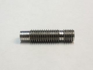
3) E3D V6. One day when removing a clog from the V5 I broke the heat break. Shipping takes forever to arrive here, so a lathe operator (? can't find the word in english) made me one.
But it didn't work as expected. The filament had trouble going all the way to the nozzle, like dragging something. And the machined part between the heater block and the heat sink is bigger than the original.
Instead of 2.8mm diameter is 4.7mm
[img]https://farm1.staticflickr.com/401/1912 ... e948_n.jpg[/img]
All right, so the V6 is working beautifully
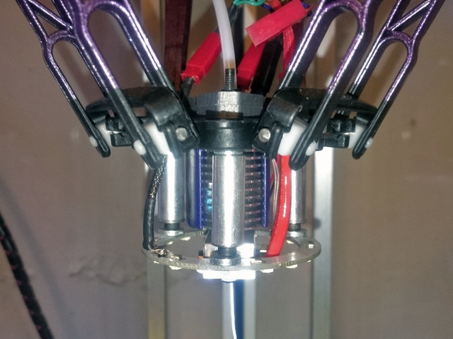
4) New mount for the V6 using the stock fan duct.
M3 nuts and bolts. I've used the stock aluminum spacers to hold the led ring.
[img]https://c1.staticflickr.com/1/738/21027 ... c59d_z.jpg[/img]
[img]https://c2.staticflickr.com/6/5647/2083 ... 4312_z.jpg[/img]
[img]https://c2.staticflickr.com/6/5769/2039 ... b7b8_z.jpg[/img]
[img]https://c1.staticflickr.com/1/712/21009 ... b8ec_z.jpg[/img]
Here is the STL and the editable Rhino file:
7) Planetary Geared Extruder.
Coming soon...
EDIT: resized images./
@626Pilot, yes I do have tower lean, but I don't have a digital angle gauge to correct it. I'm going to buy one any time soon.
I've been too lazy to update, so to sum up... changes made this far:
1) Bed running at 20v using a 24v PSU and a Fotek 100a SSR (http://forum.seemecnc.com/viewtopic.php?f=43&t=7766)
Great upgrade, one of the best thing you can do for your Max V2. It takes less than 5 min to get to 110ºc
2) 0.03" PEI sheet. I've bought this one: http://www.amazon.com/gp/product/B0013H ... ge_o00_s00
To adhere the PEI to the borosilicate plate I've used 1.25" 3M 468MP tape. It works fine, but it's almost impossible to get bubble free. If I need to do it again I would buy this: http://www.amazon.com/gp/product/B007Y7 ... UTF8&psc=1
For small prints I set the bed to 108ºc and for big ones to 100ºc. If not, it would be too difficult to remove, they won't "pop" when cooling down.
3) E3D V6. One day when removing a clog from the V5 I broke the heat break. Shipping takes forever to arrive here, so a lathe operator (? can't find the word in english) made me one.
But it didn't work as expected. The filament had trouble going all the way to the nozzle, like dragging something. And the machined part between the heater block and the heat sink is bigger than the original.
Instead of 2.8mm diameter is 4.7mm
[img]https://farm1.staticflickr.com/401/1912 ... e948_n.jpg[/img]
All right, so the V6 is working beautifully
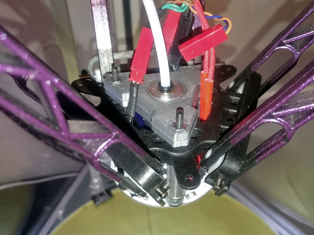
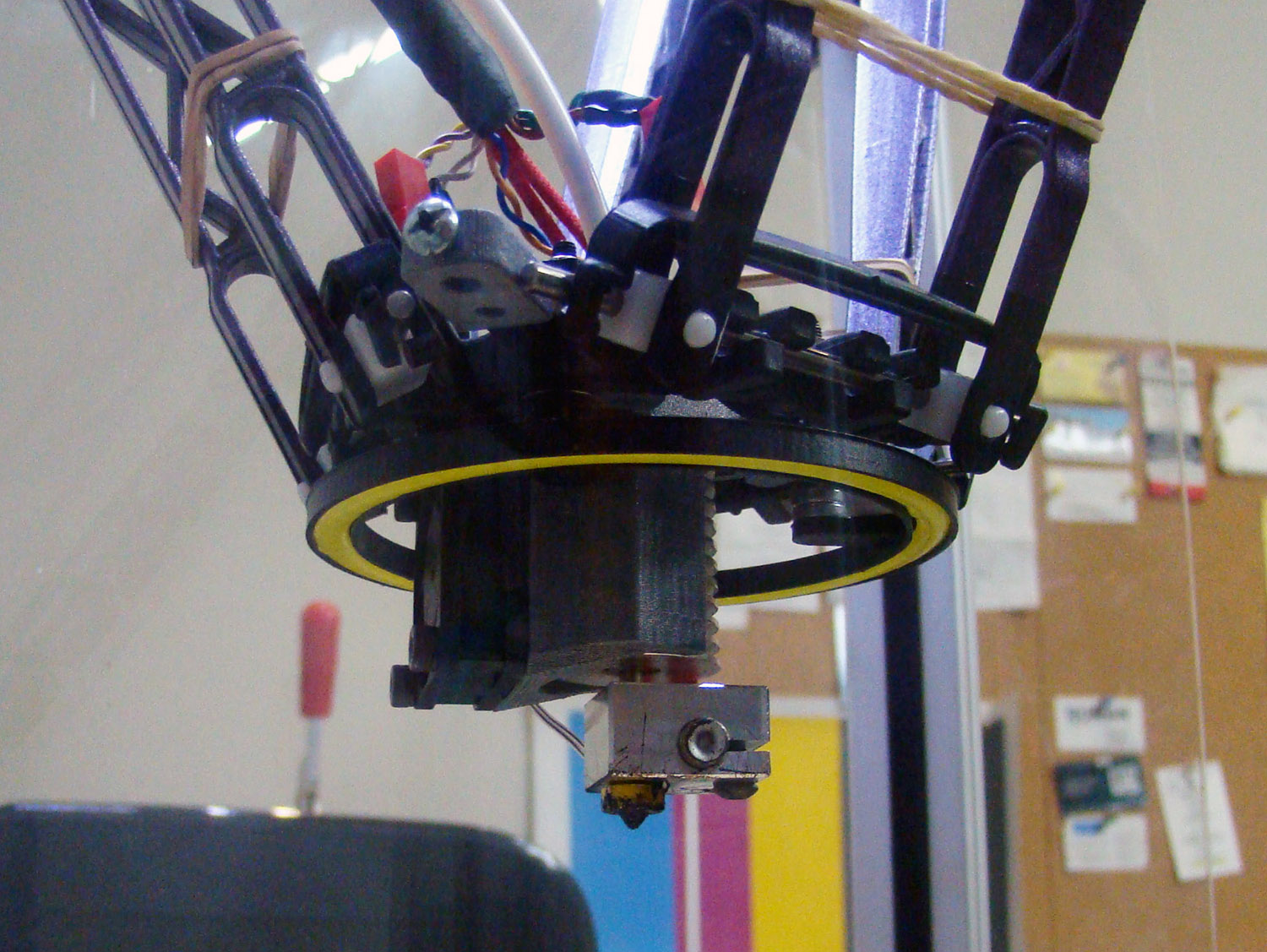
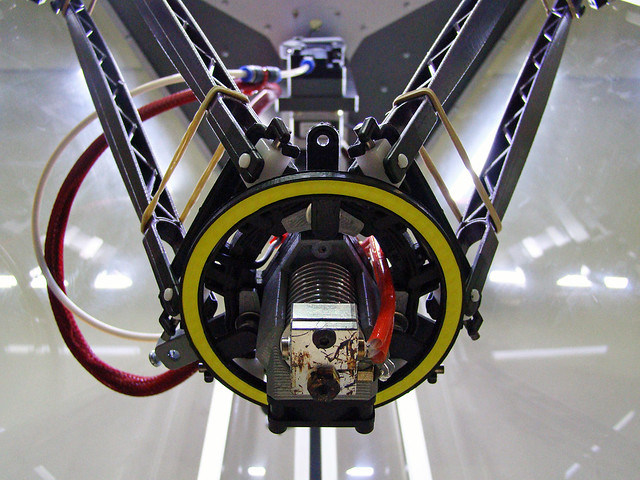
4) New mount for the V6 using the stock fan duct.
M3 nuts and bolts. I've used the stock aluminum spacers to hold the led ring.
[img]https://c1.staticflickr.com/1/738/21027 ... c59d_z.jpg[/img]
[img]https://c2.staticflickr.com/6/5647/2083 ... 4312_z.jpg[/img]
[img]https://c2.staticflickr.com/6/5769/2039 ... b7b8_z.jpg[/img]
[img]https://c1.staticflickr.com/1/712/21009 ... b8ec_z.jpg[/img]
Here is the STL and the editable Rhino file:
7) Planetary Geared Extruder.
Coming soon...
EDIT: resized images./
Last edited by Tincho85 on Fri Aug 12, 2016 7:38 pm, edited 1 time in total.
Martín S.
-
Tincho85
- Printmaster!
- Posts: 659
- Joined: Sun Nov 03, 2013 12:27 pm
- Location: Buenos Aires, Argentina
Re: Rostock Max V1.5
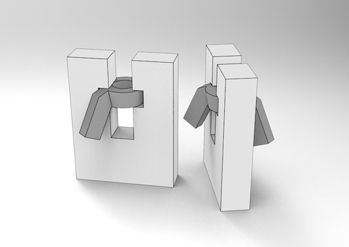
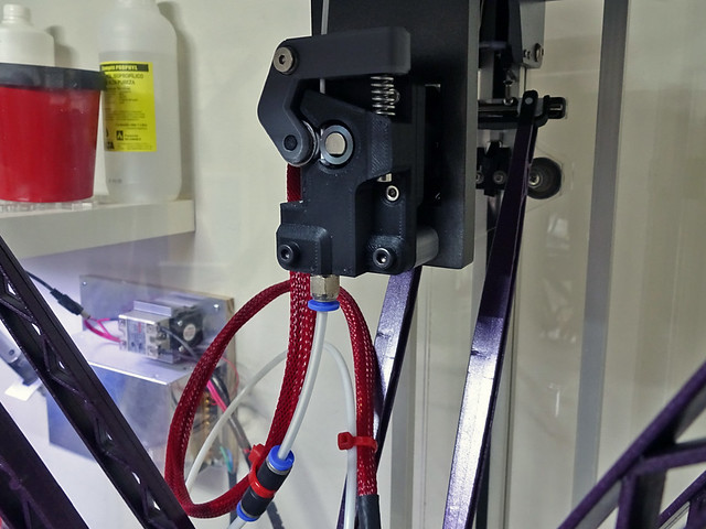
I've finally installed the geared motor. I was planning on using Glacian22 and mod it a bit, to fit a smaller bearing.
But as it was so painful to work with a STL file, I designed one from scratch.
It's a work in progress. I'm still not quite sure about how much the bearing should press against the gear.
This is a variant of Nylocke's and Glacian22 EZFlex extruder. It is a direct replacement for Seemecnc's EzStruder.
Designed for use with 1.75mm filament and a Nema 17 Planetary Geared Motor. Like Glacian22 extruder, it can handle flexible filaments very well.
Nylocke's design: http://www.youmagine.com/designs/ezflexstruder
Glacian22's design: http://www.thingiverse.com/thing:744759
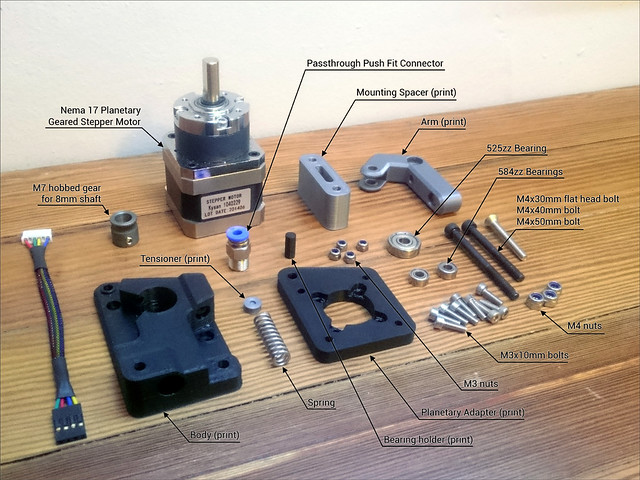
I'm not good at explaining the assembly in english, so I hope the pictures can show it clearly.
BOM:
•(x9) M3x10mm bolt
•(x4) M3 nut
•(x1) M4x30mm flat head bolt [Arm to Body. It needs to be a flat head bolt, so that the bearing can rotate freely]
•(x3) M4 nut (or nylon lock nuts)
•(x1) M4x50mm bolt [Body to Mounting Spacer to Mounting Bracket]
•(x1) M4x40mm bolt [Body to Mounting Spacer to Mounting Bracket]
•(x2) 584ZZ bearing
•(x1) 525ZZ bearing
•(x1) EzStruder Spring [don't know the specs]
•(x1) Passthrough Push Fit Connector
•(x1) Nema 17 Planetary Geared Stepper Motor (recommended ratio of 5:1)
•(x1) M7 hobbed gear for 8mm shaft
•7cm aprox of PTFE Tubing (2mm ID x 4mm OD)
Printed Parts:
•Body
•Planetary Adapter
•Arm
•Bearing Holder (you will only need one. There are 4 with different diameter so you can choose the perfect fit)
•Spring Tensioner
•OPTIONAL: Mounting Spacer (for using M4 bolts instead of the 6-32 from seemecnc. You will need to drill bigger holes to the EZStruder Mounting Bracket)
https://farm1.staticflickr.com/617/2052 ... a84b_o.jpg
[img]https://c1.staticflickr.com/1/617/20521 ... f431_z.jpg[/img]
Bill of materials.
https://farm1.staticflickr.com/705/2113 ... 43de_b.jpg
[img]https://c1.staticflickr.com/1/705/21132 ... 43de_z.jpg[/img]
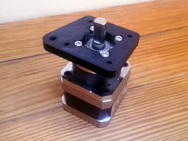
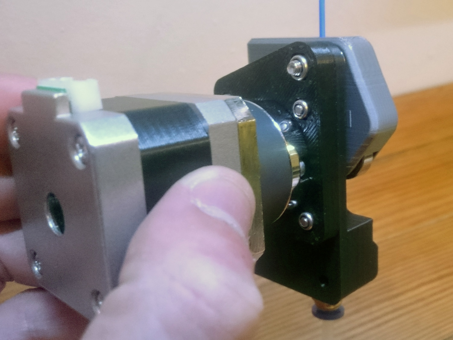
Adapter to motor.
https://farm1.staticflickr.com/694/2111 ... 3392_o.jpg
[img]https://c1.staticflickr.com/1/694/21116 ... ed47_z.jpg[/img]
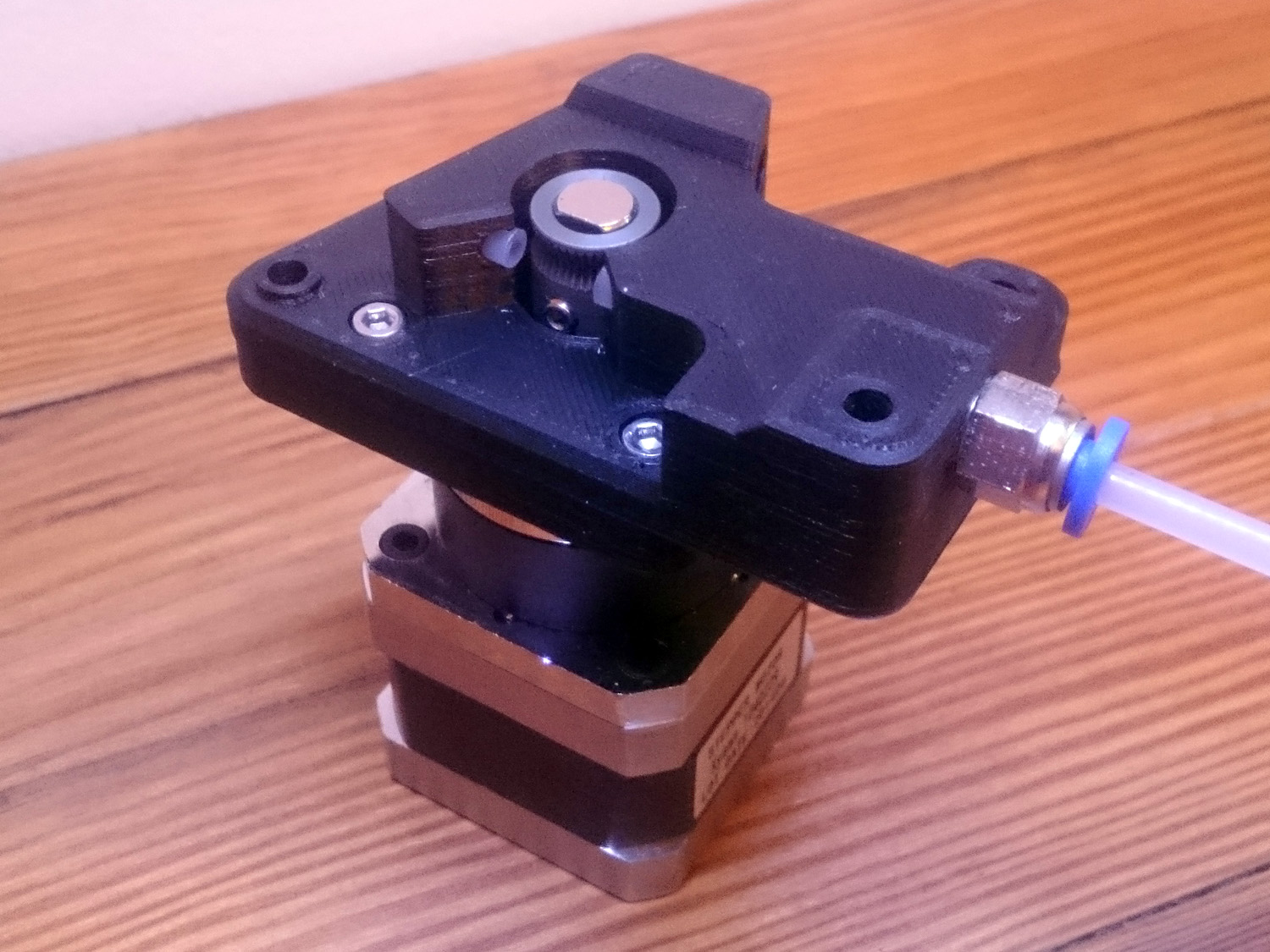
The bowden fits on both sides. Perfect for flexible filaments.
The hole where the bowden should go is 3mm in diameter. I've used a 3.9mm drill bit to make it big enough to get a very tight fit.
https://farm1.staticflickr.com/716/2095 ... f0e0_o.jpg
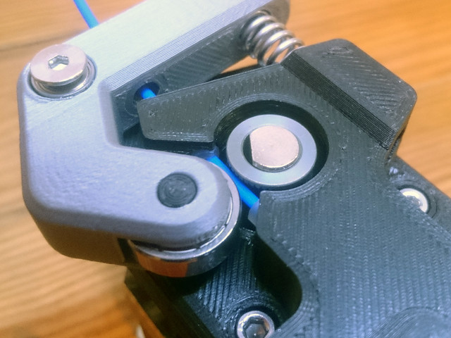
[img]https://c1.staticflickr.com/1/716/20954 ... 1b94_z.jpg[/img]
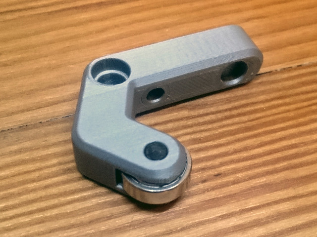
Arm with 525zz bearing installed using the bearing holder (printed).
The two 584zz bearings should go in those holes.
https://farm1.staticflickr.com/780/2111 ... 915d_o.jpg
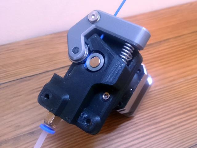
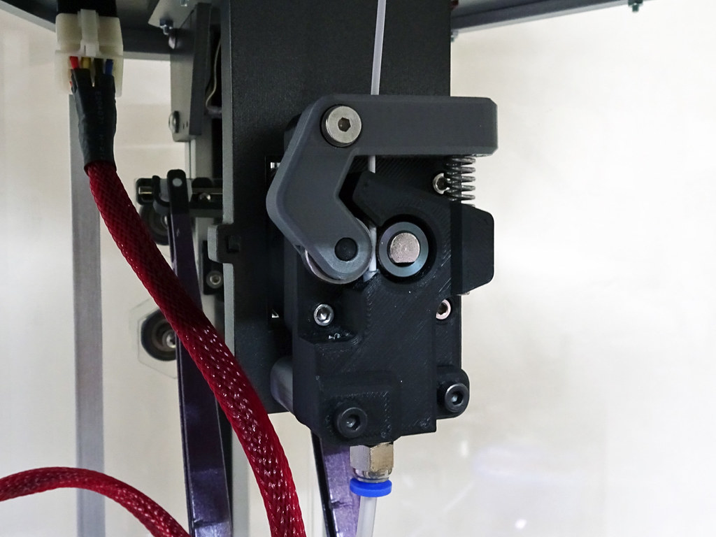
[img]https://c1.staticflickr.com/1/780/21116 ... f79e_z.jpg[/img]
https://farm6.staticflickr.com/5825/211 ... d326_o.jpg
[img]https://c2.staticflickr.com/6/5825/2113 ... 3041_z.jpg[/img]
https://farm1.staticflickr.com/654/2115 ... 939c_o.jpg
[img]https://c1.staticflickr.com/1/654/21150 ... a6be_z.jpg[/img]
https://farm1.staticflickr.com/683/2109 ... d345_b.jpg
[img]https://c1.staticflickr.com/1/683/21094 ... d345_z.jpg[/img]
https://farm6.staticflickr.com/5811/209 ... 616e_o.jpg
[img]https://c2.staticflickr.com/6/5811/2095 ... 6753_z.jpg[/img]
The bowden tube was too short, so instead of replacing it I've used an adapter.
http://www.thingiverse.com/thing:998188
EDIT: resized images./
But as it was so painful to work with a STL file, I designed one from scratch.
It's a work in progress. I'm still not quite sure about how much the bearing should press against the gear.
This is a variant of Nylocke's and Glacian22 EZFlex extruder. It is a direct replacement for Seemecnc's EzStruder.
Designed for use with 1.75mm filament and a Nema 17 Planetary Geared Motor. Like Glacian22 extruder, it can handle flexible filaments very well.
Nylocke's design: http://www.youmagine.com/designs/ezflexstruder
Glacian22's design: http://www.thingiverse.com/thing:744759
I'm not good at explaining the assembly in english, so I hope the pictures can show it clearly.
BOM:
•(x9) M3x10mm bolt
•(x4) M3 nut
•(x1) M4x30mm flat head bolt [Arm to Body. It needs to be a flat head bolt, so that the bearing can rotate freely]
•(x3) M4 nut (or nylon lock nuts)
•(x1) M4x50mm bolt [Body to Mounting Spacer to Mounting Bracket]
•(x1) M4x40mm bolt [Body to Mounting Spacer to Mounting Bracket]
•(x2) 584ZZ bearing
•(x1) 525ZZ bearing
•(x1) EzStruder Spring [don't know the specs]
•(x1) Passthrough Push Fit Connector
•(x1) Nema 17 Planetary Geared Stepper Motor (recommended ratio of 5:1)
•(x1) M7 hobbed gear for 8mm shaft
•7cm aprox of PTFE Tubing (2mm ID x 4mm OD)
Printed Parts:
•Body
•Planetary Adapter
•Arm
•Bearing Holder (you will only need one. There are 4 with different diameter so you can choose the perfect fit)
•Spring Tensioner
•OPTIONAL: Mounting Spacer (for using M4 bolts instead of the 6-32 from seemecnc. You will need to drill bigger holes to the EZStruder Mounting Bracket)
https://farm1.staticflickr.com/617/2052 ... a84b_o.jpg
[img]https://c1.staticflickr.com/1/617/20521 ... f431_z.jpg[/img]
Bill of materials.
https://farm1.staticflickr.com/705/2113 ... 43de_b.jpg
[img]https://c1.staticflickr.com/1/705/21132 ... 43de_z.jpg[/img]
Adapter to motor.
https://farm1.staticflickr.com/694/2111 ... 3392_o.jpg
[img]https://c1.staticflickr.com/1/694/21116 ... ed47_z.jpg[/img]
The bowden fits on both sides. Perfect for flexible filaments.
The hole where the bowden should go is 3mm in diameter. I've used a 3.9mm drill bit to make it big enough to get a very tight fit.
https://farm1.staticflickr.com/716/2095 ... f0e0_o.jpg
[img]https://c1.staticflickr.com/1/716/20954 ... 1b94_z.jpg[/img]
Arm with 525zz bearing installed using the bearing holder (printed).
The two 584zz bearings should go in those holes.
https://farm1.staticflickr.com/780/2111 ... 915d_o.jpg
[img]https://c1.staticflickr.com/1/780/21116 ... f79e_z.jpg[/img]
https://farm6.staticflickr.com/5825/211 ... d326_o.jpg
[img]https://c2.staticflickr.com/6/5825/2113 ... 3041_z.jpg[/img]
https://farm1.staticflickr.com/654/2115 ... 939c_o.jpg
[img]https://c1.staticflickr.com/1/654/21150 ... a6be_z.jpg[/img]
https://farm1.staticflickr.com/683/2109 ... d345_b.jpg
[img]https://c1.staticflickr.com/1/683/21094 ... d345_z.jpg[/img]
https://farm6.staticflickr.com/5811/209 ... 616e_o.jpg
[img]https://c2.staticflickr.com/6/5811/2095 ... 6753_z.jpg[/img]
The bowden tube was too short, so instead of replacing it I've used an adapter.
http://www.thingiverse.com/thing:998188
EDIT: resized images./
Last edited by Tincho85 on Fri Aug 12, 2016 7:26 pm, edited 1 time in total.
Martín S.
Re: Rostock Max V1.5
That's pretty good! I already have three EZStruders and geared motors, and an adapter plate I made to fit them together. I was thinking about drilling out the plastic so that I could feed the PTFE all the way to the hobbed bolt.
Questions? Ask in a thread - PMs are off.
AI Calibration | Dimensional Accuracy Calibration | Hand-Tune your PID | OctoPi + Touchscreen setup | My E3D hot end mount, Z probe, fan ducts, LED ring mount, filament spool holder, etc.
AI Calibration | Dimensional Accuracy Calibration | Hand-Tune your PID | OctoPi + Touchscreen setup | My E3D hot end mount, Z probe, fan ducts, LED ring mount, filament spool holder, etc.
-
Tincho85
- Printmaster!
- Posts: 659
- Joined: Sun Nov 03, 2013 12:27 pm
- Location: Buenos Aires, Argentina
Re: Rostock Max V1.5
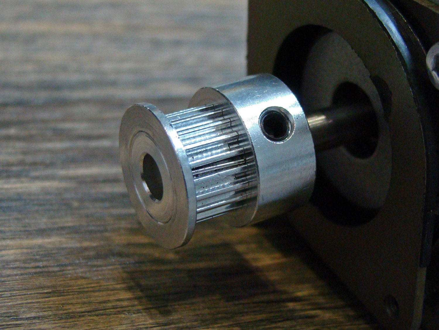
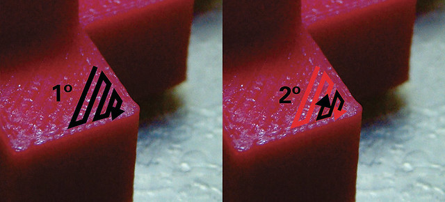
I think my tower lean got fixed. I bought a digital miter finder and measured all of them.
X: 89.9º
Y: 90.0º
Z: 90.6º
I couldn't correct Z perfectly, but now it's 90.1º. X and Y were left untouched.
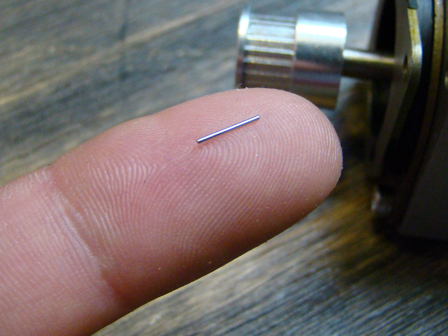
Also... please check your timing pulleys. Two of them had a little piece of metal in one tooth, dunno how it got there.
https://c2.staticflickr.com/6/5774/2161 ... 3e54_o.jpg
[img]https://c2.staticflickr.com/6/5774/2161 ... 4378_z.jpg[/img]
https://c2.staticflickr.com/6/5765/2161 ... 2bbe_o.jpg
[img]https://c2.staticflickr.com/6/5765/2161 ... ffda_z.jpg[/img]
X: 89.9º
Y: 90.0º
Z: 90.6º
I couldn't correct Z perfectly, but now it's 90.1º. X and Y were left untouched.
Also... please check your timing pulleys. Two of them had a little piece of metal in one tooth, dunno how it got there.
https://c2.staticflickr.com/6/5774/2161 ... 3e54_o.jpg
[img]https://c2.staticflickr.com/6/5774/2161 ... 4378_z.jpg[/img]
https://c2.staticflickr.com/6/5765/2161 ... 2bbe_o.jpg
[img]https://c2.staticflickr.com/6/5765/2161 ... ffda_z.jpg[/img]
Martín S.
-
Tincho85
- Printmaster!
- Posts: 659
- Joined: Sun Nov 03, 2013 12:27 pm
- Location: Buenos Aires, Argentina
Re: Rostock Max V1.5
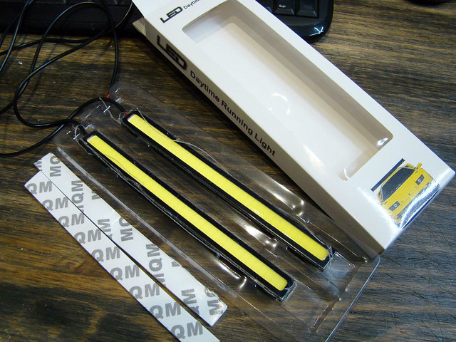
The led light ring of the effector is one thing I both love and hate.
It lets you watch clearly when it's printing and it looks very cool, but it's a pain in the... when the hotend is below the effector. It's always in the way.
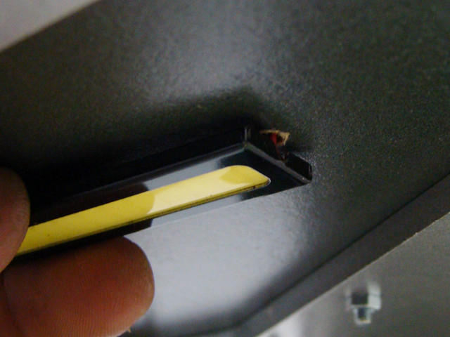
So I bough some cob leds that are used for tunning. They come with 3M tape making the install very easy.
https://c2.staticflickr.com/6/5721/2206 ... b971_o.jpg
[img]https://c2.staticflickr.com/6/5721/2206 ... 95f6_z.jpg[/img]
This is the product. I bought the one that is 170mm long
http://www.ebay.com/itm/2pcs-High-Power ... XfKmL-tW1w
https://c1.staticflickr.com/1/731/22256 ... 6f6a_o.jpg
[img]https://c1.staticflickr.com/1/731/22256 ... a5bf_z.jpg[/img]
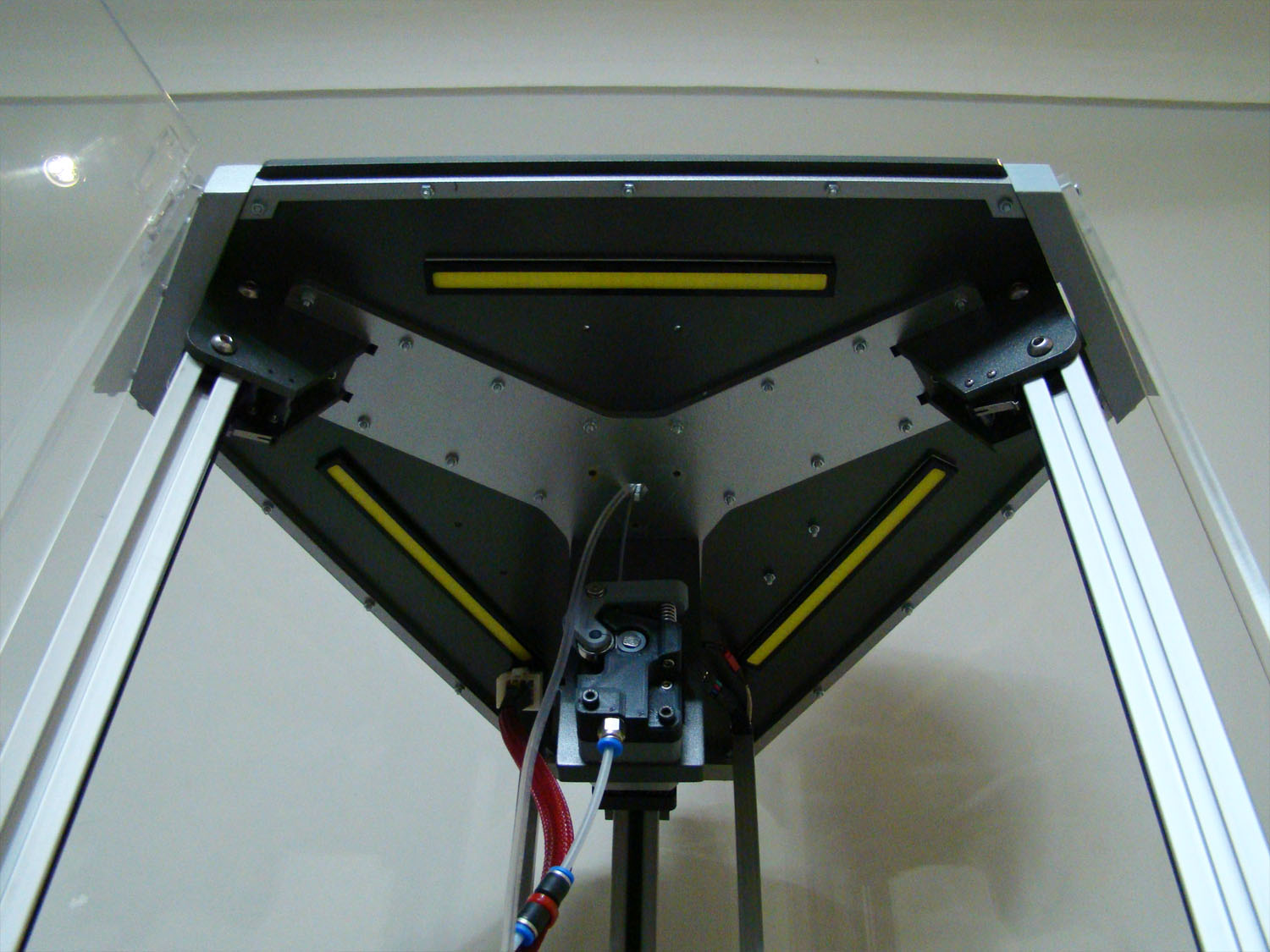
Just drill one hole for the cables. I've connected directly to the psu so it turns on with the machine.
https://c1.staticflickr.com/1/593/22069 ... 7f9b_o.jpg
[img]https://c1.staticflickr.com/1/593/22069 ... cebb_z.jpg[/img]
https://c1.staticflickr.com/1/698/22069 ... 9792_o.jpg
[img]https://c1.staticflickr.com/1/698/22069 ... 9fe3_z.jpg[/img]
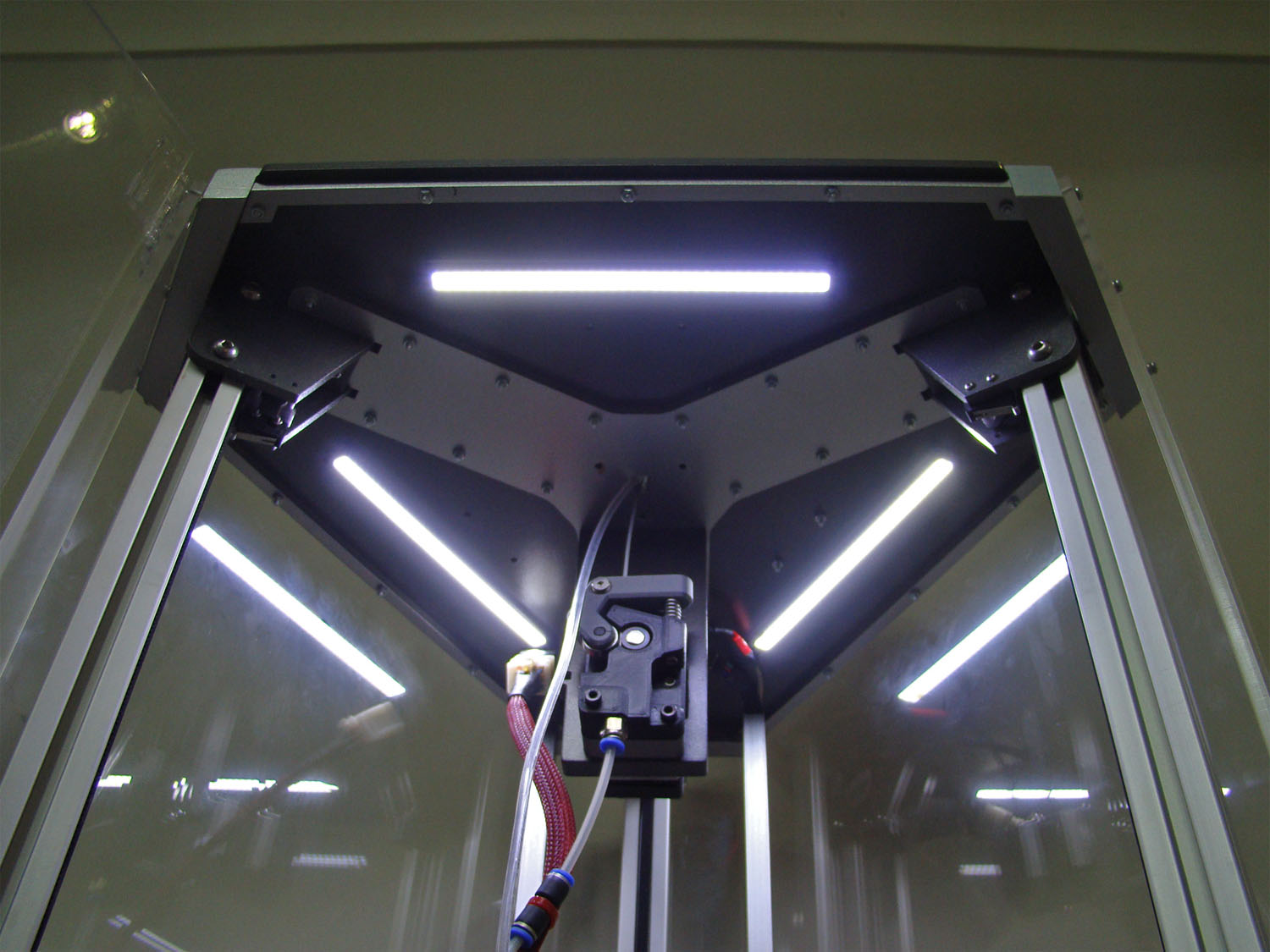
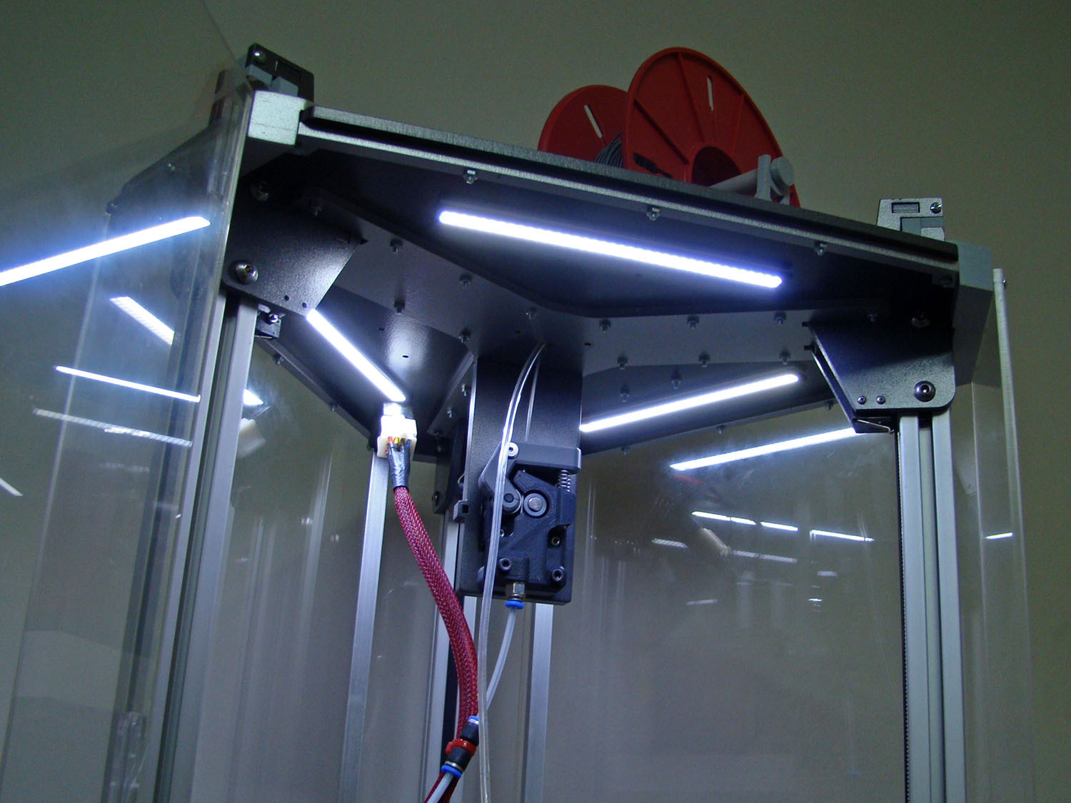
and... lights on!
https://c1.staticflickr.com/1/741/22068 ... 6cb3_o.jpg
[img]https://c1.staticflickr.com/1/741/22068 ... f440_z.jpg[/img]
https://c2.staticflickr.com/6/5763/2224 ... 6274_o.jpg
[img]https://c2.staticflickr.com/6/5763/2224 ... b7d5_z.jpg[/img]
Let me know if you install them.
I'm very happy with them.
EDIT: resized images./
It lets you watch clearly when it's printing and it looks very cool, but it's a pain in the... when the hotend is below the effector. It's always in the way.
So I bough some cob leds that are used for tunning. They come with 3M tape making the install very easy.
https://c2.staticflickr.com/6/5721/2206 ... b971_o.jpg
[img]https://c2.staticflickr.com/6/5721/2206 ... 95f6_z.jpg[/img]
This is the product. I bought the one that is 170mm long
http://www.ebay.com/itm/2pcs-High-Power ... XfKmL-tW1w
https://c1.staticflickr.com/1/731/22256 ... 6f6a_o.jpg
[img]https://c1.staticflickr.com/1/731/22256 ... a5bf_z.jpg[/img]
Just drill one hole for the cables. I've connected directly to the psu so it turns on with the machine.
https://c1.staticflickr.com/1/593/22069 ... 7f9b_o.jpg
[img]https://c1.staticflickr.com/1/593/22069 ... cebb_z.jpg[/img]
https://c1.staticflickr.com/1/698/22069 ... 9792_o.jpg
[img]https://c1.staticflickr.com/1/698/22069 ... 9fe3_z.jpg[/img]
and... lights on!
https://c1.staticflickr.com/1/741/22068 ... 6cb3_o.jpg
[img]https://c1.staticflickr.com/1/741/22068 ... f440_z.jpg[/img]
https://c2.staticflickr.com/6/5763/2224 ... 6274_o.jpg
[img]https://c2.staticflickr.com/6/5763/2224 ... b7d5_z.jpg[/img]
Let me know if you install them.
I'm very happy with them.
EDIT: resized images./
Last edited by Tincho85 on Fri Aug 12, 2016 7:17 pm, edited 1 time in total.
Martín S.
Re: Rostock Max V1.5
Those lights will add at LEAST 10hp too! 
g.
(they look great!)
g.
(they look great!)
Delta Power!
Defeat the Cartesian Agenda!
http://www.f15sim.com - 80-0007, The only one of its kind.
http://geneb.simpits.org - Technical and Simulator Projects
Defeat the Cartesian Agenda!
http://www.f15sim.com - 80-0007, The only one of its kind.
http://geneb.simpits.org - Technical and Simulator Projects

Re: Rostock Max V1.5
I'm pretty sure if they were red you would be able to print at least 100mm/s faster
-
Tincho85
- Printmaster!
- Posts: 659
- Joined: Sun Nov 03, 2013 12:27 pm
- Location: Buenos Aires, Argentina
Re: Rostock Max V1.5
Yeahhh now it's nice to see it printing while the other lights are turned off.
I think the shifting issue is solved. It was like 626Pilot said, a blob due to over-extrusion that moved the platform while printing. To fix this, I've modified several factors, E steps, oozing, wipe while retract and z lift.
I did the calibration for the extruder, both the ez-struder and the planetary. Extruding 100mm was exactly 100mm but what I didn't take in consideration was this:
When I had “wipe while retract” activated, after printing a corner or small perimeters the nozzle moved backwards following the pattern previously printed. This combiend with the oozing, lefted a big mess of filament.
Approximate movement:
[img]https://c1.staticflickr.com/1/758/22692 ... 6b80_z.jpg[/img]
1) Movement for printing.
2) the "wipe"
and Z lift was increased from 0,5 to 1mm.
I think the shifting issue is solved. It was like 626Pilot said, a blob due to over-extrusion that moved the platform while printing. To fix this, I've modified several factors, E steps, oozing, wipe while retract and z lift.
I did the calibration for the extruder, both the ez-struder and the planetary. Extruding 100mm was exactly 100mm but what I didn't take in consideration was this:
Long story short, my E steps were 472 and now 441. To get to this number I've followed Triffid Hunter's fine tuning guide, this step:“The back-pressure from the hot-end alters how much plastic each hob revolution pushes, and you'll probably end up tightening your idler more which reduces the hob effective diameter.”
http://reprap.org/wiki/Triffid_Hunter%2 ... tion_Guide1. Find an object with flat tops on a number of levels, such as this cube stack test (scale this object by 250% after loading in Slic3r)
2. Slice at 95% rectilinear infill. Use the lowest layer height you're comfortable with - the lower the layer height used for this test, the finer your resulting E steps calibration will be. I use 0.2mm for first run, and if I'm feeling ambitious I'll repeat this process at 0.1mm.
3. Print.
4. Ignore the first 5-6 layers because they're too sensitive to the exact height of the first layer. If it's obviously over-filling or under-filling, alter E steps or Z=0 point and restart the print.
5. Observe infill. If you can't see tiny little gaps between the lines, reduce E steps by 0.5% every 2 layers until you can see tiny gaps.
6. Observe solid top layers. If you can see tiny gaps, increase E steps by 0.5% every 2 layers until there's no gaps in the top.
7. Send the new E steps to your printer with M92 Ennn without even pausing the print - you will see the result in a couple of layers when the change is this small.
8. Goto 5 until the infill has tiny gaps AND the solid top layers do not.
9. Now, your E steps value is extremely fine-tuned! Save this value in your firmware's configuration and flash to make permanent.
When I had “wipe while retract” activated, after printing a corner or small perimeters the nozzle moved backwards following the pattern previously printed. This combiend with the oozing, lefted a big mess of filament.
Approximate movement:
[img]https://c1.staticflickr.com/1/758/22692 ... 6b80_z.jpg[/img]
1) Movement for printing.
2) the "wipe"
and Z lift was increased from 0,5 to 1mm.
Martín S.
-
Tincho85
- Printmaster!
- Posts: 659
- Joined: Sun Nov 03, 2013 12:27 pm
- Location: Buenos Aires, Argentina
Re: Rostock Max V1.5
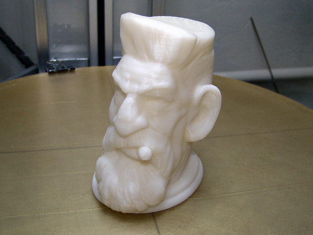
Hello, just wanted to share a print. One at least I'm proud of  , and of course never been possible without the help of this great community.
Natural White ABS
0.2 layer height (I think, or 0.25)
0.4 nozzle
https://c1.staticflickr.com/1/667/22772 ... 418c_o.jpg
[img]https://c1.staticflickr.com/1/667/22772 ... 33ed_z.jpg[/img]
This is the model, if anyone is interested
http://www.thingiverse.com/thing:69709
Natural White ABS
0.2 layer height (I think, or 0.25)
0.4 nozzle
https://c1.staticflickr.com/1/667/22772 ... 418c_o.jpg
[img]https://c1.staticflickr.com/1/667/22772 ... 33ed_z.jpg[/img]
This is the model, if anyone is interested
http://www.thingiverse.com/thing:69709
Martín S.
-
derzaubererer
- Printmaster!
- Posts: 70
- Joined: Tue Aug 25, 2015 10:15 am
Re: Rostock Max V1.5
verz nice and clean build i really love the lights and the cold end
also very good quality on your print:)
also very good quality on your print:)
-
Tincho85
- Printmaster!
- Posts: 659
- Joined: Sun Nov 03, 2013 12:27 pm
- Location: Buenos Aires, Argentina
Re: Rostock Max V1.5
Thanks derzaubererer!
Grrhhh... I miss my light ring.
Now it's a light station more than a 3d printer though.
I've chosen this size of ring so that it doesn't interfere with the fan of the E3D V6 hotend.
The ring snaps only at 3 places. Making it very easy to install/remove from the case.
https://c2.staticflickr.com/6/5685/2286 ... 9885_o.jpg
[img]https://c2.staticflickr.com/6/5685/2286 ... a027_z.jpg[/img]
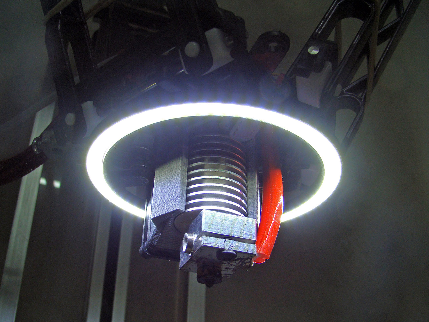
The friking ring in action!
https://c2.staticflickr.com/6/5750/2243 ... 9984_o.jpg
[img]https://c2.staticflickr.com/6/5750/2243 ... 092e_z.jpg[/img]
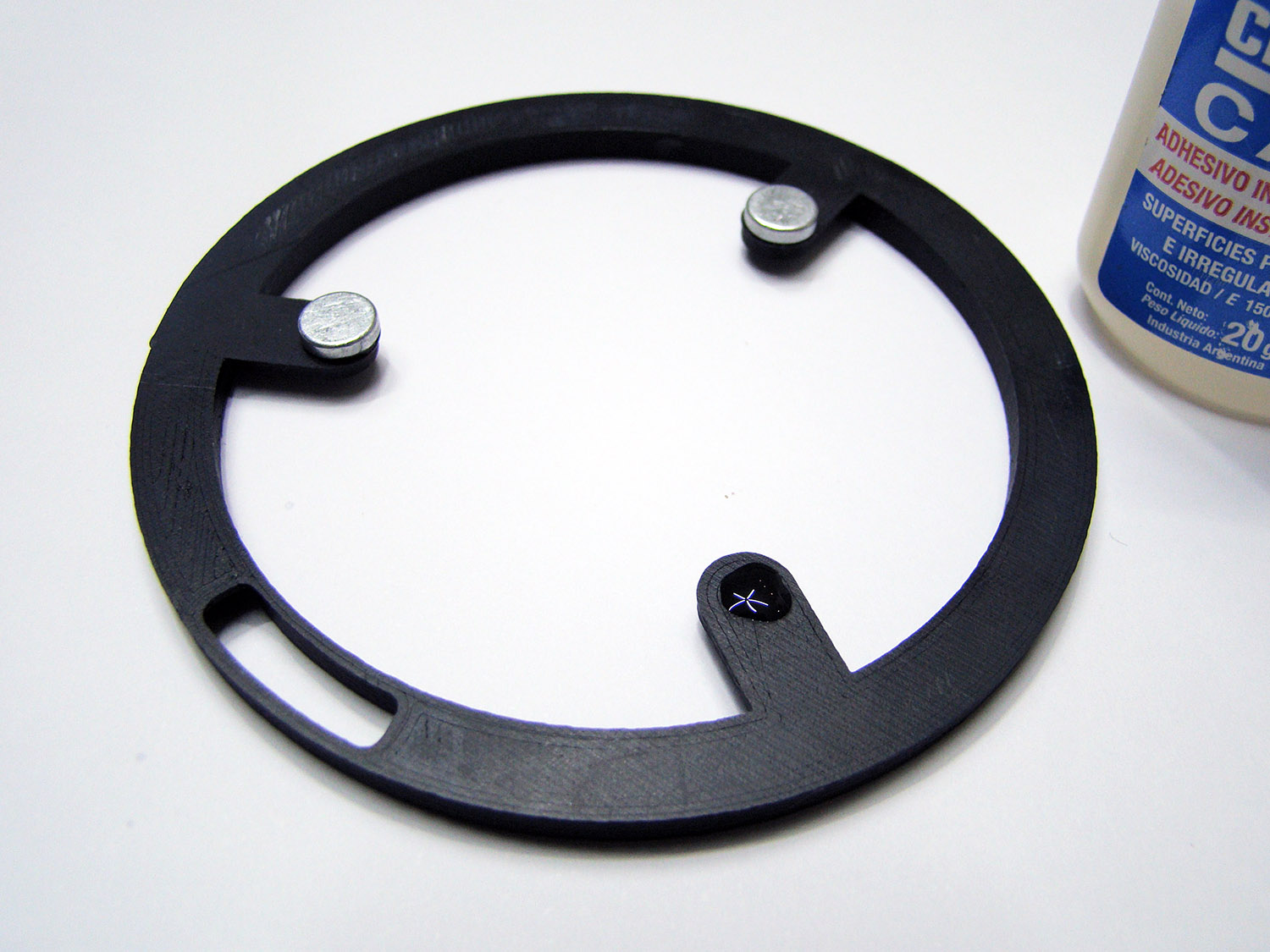
I've used cyanoacrylate (superglue) to paste the magnets to the case.
Magnets: Diameter 9mm, Height 2mm, (x6) or use larger ones.
https://c1.staticflickr.com/1/633/22841 ... 5f20_o.jpg
[img]https://c1.staticflickr.com/1/633/22841 ... 0289_z.jpg[/img]
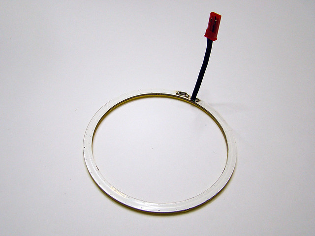
And this is the ring. 80mm COB LED Light Ring. Outer Diameter 79.35mm, Inner Diameter 70.65mm
I think this one is the same: http://www.aliexpress.com/store/product ... 87928.html
https://c1.staticflickr.com/1/597/22829 ... edec_o.jpg
[img]https://c1.staticflickr.com/1/597/22829 ... d5ed_z.jpg[/img]
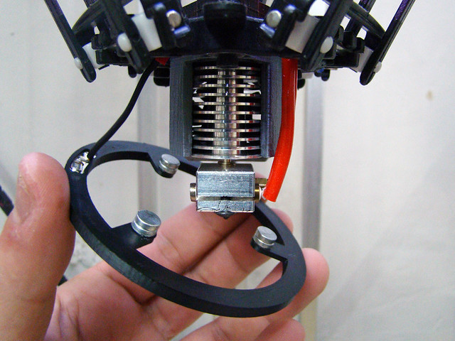
To hold it you must use standard bolts. Stainless steel ones won't work.
https://c2.staticflickr.com/6/5659/2223 ... 9290_o.jpg
[img]https://c2.staticflickr.com/6/5659/2223 ... 041d_z.jpg[/img]
https://c1.staticflickr.com/1/689/22841 ... e986_o.jpg
[img]https://c1.staticflickr.com/1/689/22841 ... cbfe_z.jpg[/img]
https://c1.staticflickr.com/1/660/22855 ... 9bba_o.jpg
[img]https://c1.staticflickr.com/1/660/22855 ... f53d_z.jpg[/img]
Thingiverse: http://www.thingiverse.com/thing:1117593" onclick="window.open(this.href);return false;
More pics. https://www.flickr.com/photos/66453376@ ... 8619212333" onclick="window.open(this.href);return false;
If someone wants the cad file just ask.
Grrhhh... I miss my light ring.
Now it's a light station more than a 3d printer though.
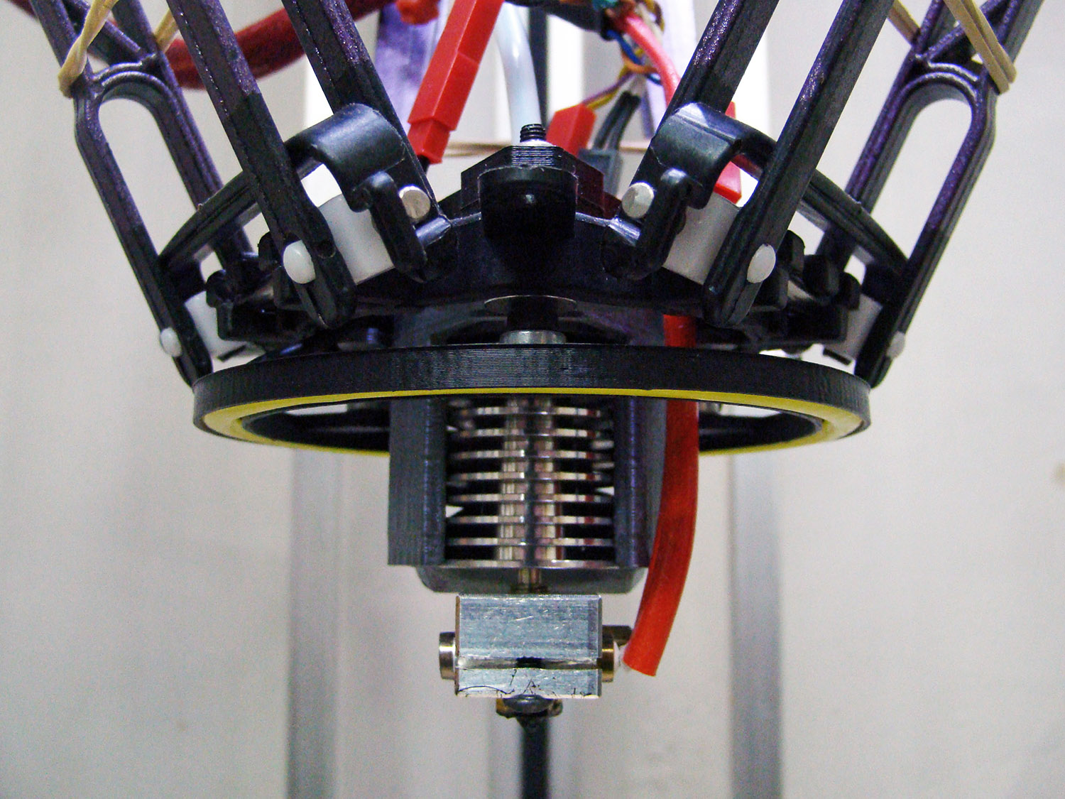
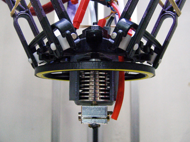
I've chosen this size of ring so that it doesn't interfere with the fan of the E3D V6 hotend.
The ring snaps only at 3 places. Making it very easy to install/remove from the case.
https://c2.staticflickr.com/6/5685/2286 ... 9885_o.jpg
[img]https://c2.staticflickr.com/6/5685/2286 ... a027_z.jpg[/img]
The friking ring in action!
https://c2.staticflickr.com/6/5750/2243 ... 9984_o.jpg
[img]https://c2.staticflickr.com/6/5750/2243 ... 092e_z.jpg[/img]
I've used cyanoacrylate (superglue) to paste the magnets to the case.
Magnets: Diameter 9mm, Height 2mm, (x6) or use larger ones.
https://c1.staticflickr.com/1/633/22841 ... 5f20_o.jpg
[img]https://c1.staticflickr.com/1/633/22841 ... 0289_z.jpg[/img]
And this is the ring. 80mm COB LED Light Ring. Outer Diameter 79.35mm, Inner Diameter 70.65mm
I think this one is the same: http://www.aliexpress.com/store/product ... 87928.html
https://c1.staticflickr.com/1/597/22829 ... edec_o.jpg
[img]https://c1.staticflickr.com/1/597/22829 ... d5ed_z.jpg[/img]
To hold it you must use standard bolts. Stainless steel ones won't work.
https://c2.staticflickr.com/6/5659/2223 ... 9290_o.jpg
[img]https://c2.staticflickr.com/6/5659/2223 ... 041d_z.jpg[/img]
https://c1.staticflickr.com/1/689/22841 ... e986_o.jpg
[img]https://c1.staticflickr.com/1/689/22841 ... cbfe_z.jpg[/img]
https://c1.staticflickr.com/1/660/22855 ... 9bba_o.jpg
[img]https://c1.staticflickr.com/1/660/22855 ... f53d_z.jpg[/img]
Thingiverse: http://www.thingiverse.com/thing:1117593" onclick="window.open(this.href);return false;
More pics. https://www.flickr.com/photos/66453376@ ... 8619212333" onclick="window.open(this.href);return false;
If someone wants the cad file just ask.
Martín S.
-
Tincho85
- Printmaster!
- Posts: 659
- Joined: Sun Nov 03, 2013 12:27 pm
- Location: Buenos Aires, Argentina
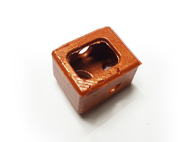
E3D V6 Heatshield
A few days ago I saw a prototype of E3D's heater block cover and it was amazing. That made want to make one. Jim posted several links of them and I did try to make one, but it failed. The problem with most of the molds on thingiverse is that they don't show how the casting should be done.
So I designed one to fit my needs. If someone is serious about making one, lets hope this guide helps.
I wanted the silicone to cover the edges of the nozzle and to be compatible with the M3 screw-on thermistor by rp one labs.
https://c2.staticflickr.com/8/7663/2805 ... d775_o.jpg
[img]https://c2.staticflickr.com/8/7663/2805 ... cf6d_z.jpg[/img]
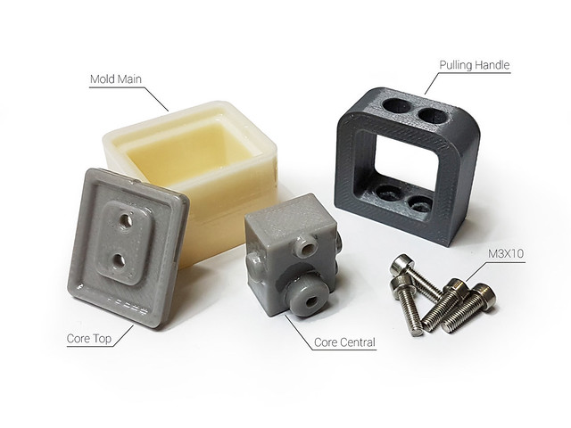
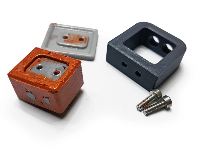
BOM list: 4 printed parts and 4 M3x10mm screws. M3x8 or M3x12 will also work.
Parts were printed in ABS and then given an acetone bath. Besides making a smoother surface, it eliminates the cavities between layers and make a painless extraction.
https://c2.staticflickr.com/8/7443/2802 ... ce82_o.jpg
[img]https://c2.staticflickr.com/8/7443/2802 ... 358d_z.jpg[/img]
The mold was filled using Permatex Ultra Copper RTV because that's what I had at the moment. But using two-component high temperature silicone will be much easier to cast and with better looking results. It's better to put more than less, so the mold overflows a bit.
https://c2.staticflickr.com/8/7409/2802 ... 3f42_o.jpg
[img]https://c2.staticflickr.com/8/7409/2802 ... 7133_z.jpg[/img]
Double check the orientation. I did it wrong the first time.
https://c2.staticflickr.com/8/7439/2805 ... 767e_o.jpg
[img]https://c2.staticflickr.com/8/7439/2805 ... 38a4_z.jpg[/img]
Use two M3x10 screws to fix the “Core Central” to the “Mold Main”.
https://c2.staticflickr.com/8/7412/2805 ... d3c5_o.jpg
[img]https://c2.staticflickr.com/8/7412/2805 ... 2f31_z.jpg[/img]
Looking good!
https://c2.staticflickr.com/8/7472/2805 ... 3bc0_o.jpg
[img]https://c2.staticflickr.com/8/7472/2805 ... cb85_z.jpg[/img]
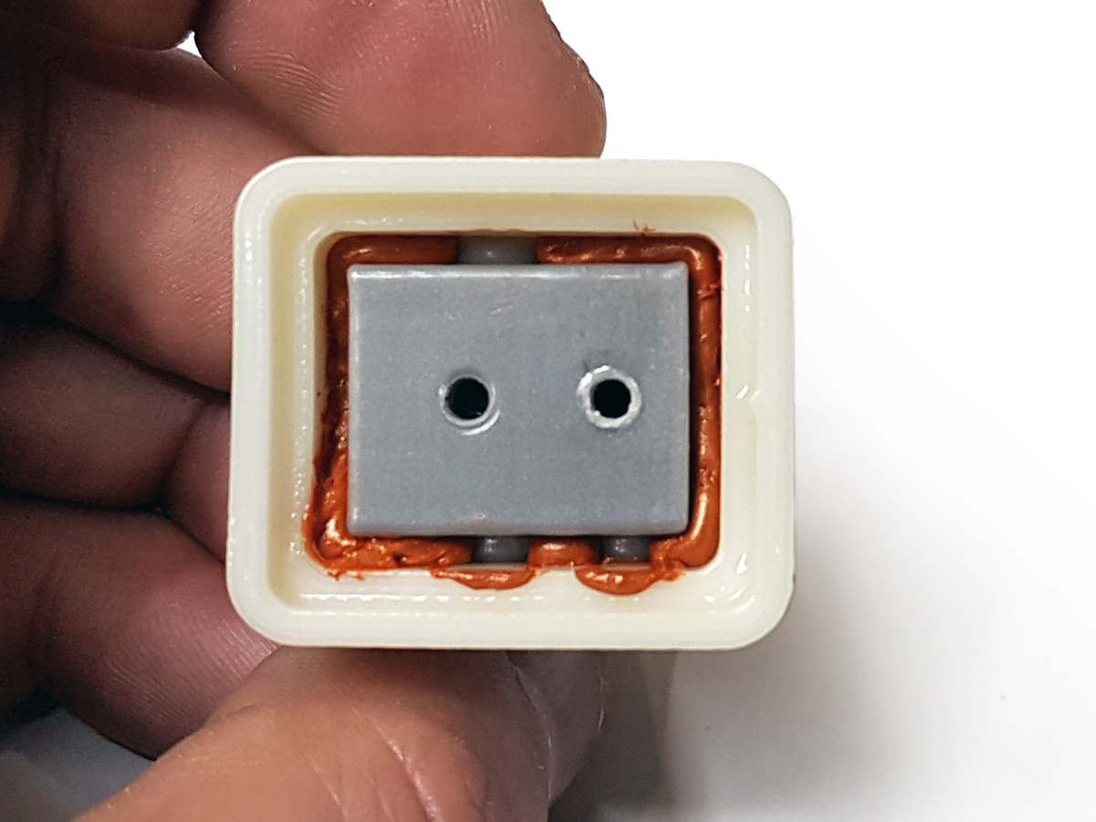
Now fill the “Mold Main” with more silicone. Notice the two marks on the edges, they work as a guideline to show the proper orientation of parts.
https://c2.staticflickr.com/8/7299/2805 ... acd6_o.jpg
[img]https://c2.staticflickr.com/8/7299/2805 ... dba9_z.jpg[/img]
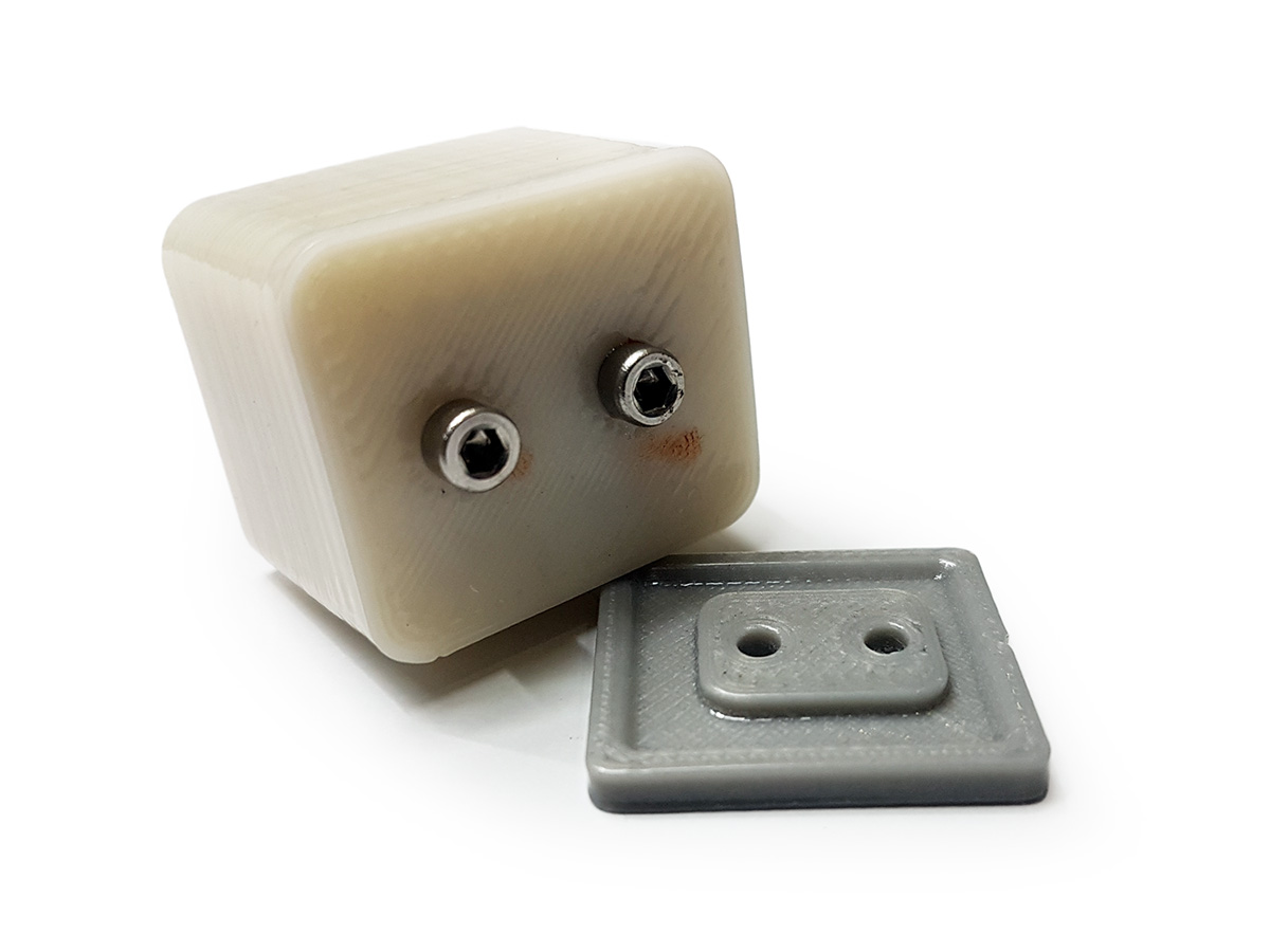
Insert the “Core Top” and press it tight with your fingers. Some silicone may overflow. Then, put the “Pulling Handle” and tighten everything using two M3X10mm screws.
https://c2.staticflickr.com/8/7454/2777 ... b1b6_o.jpg
[img]https://c2.staticflickr.com/8/7454/2777 ... b981_z.jpg[/img]
Let it dry. Just to be safe, I left the Permatex 20 hours aprox.
https://c2.staticflickr.com/8/7556/2805 ... 9bfd_o.jpg
[img]https://c2.staticflickr.com/8/7556/2805 ... 9c3b_z.jpg[/img]
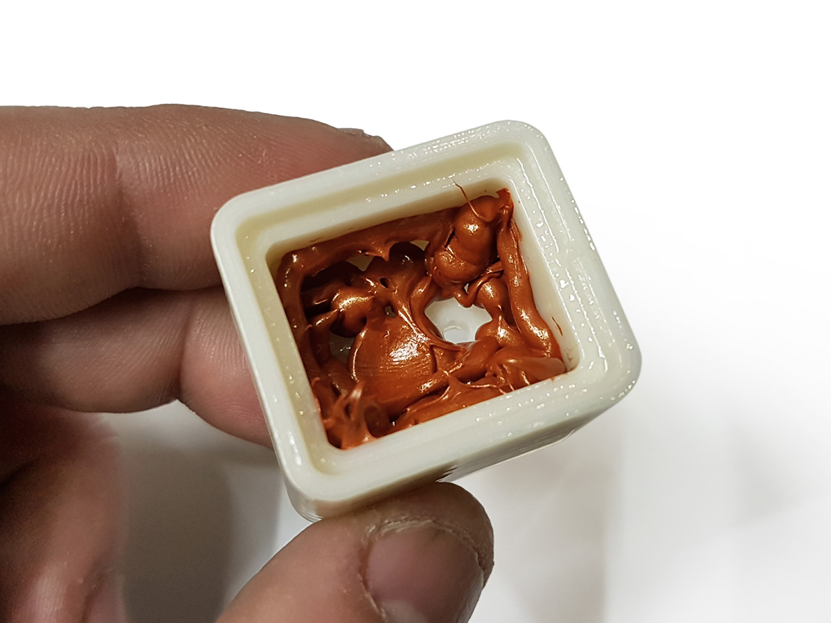
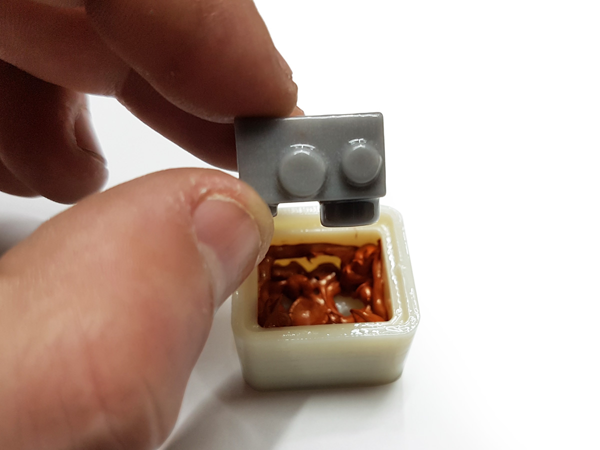
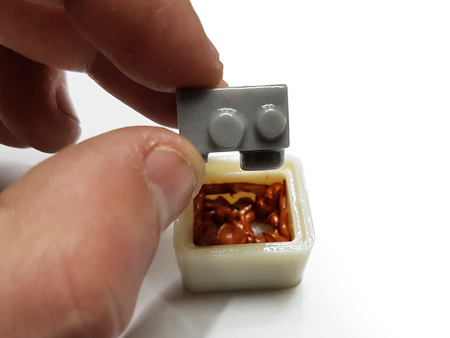
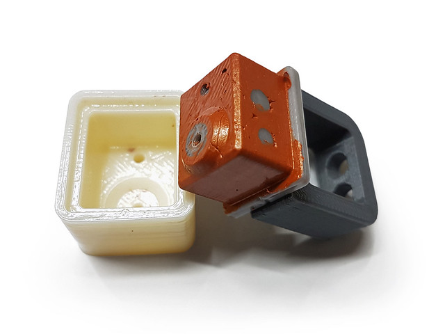
Remove only the two bottom screws and pull gently. The Permatex Ultra Copper RTV is not structurally strong.
https://c2.staticflickr.com/8/7322/2797 ... 1567_o.jpg
[img]https://c2.staticflickr.com/8/7322/2797 ... 0efc_z.jpg[/img]
Mine came out with some scars, but it will work. If you use proper two-component high temperature silicone, it will be easier to get a smoother finish because it’s more liquid.
To be continued...
Now I remember why I never update this, it takes a lot of time to record everything lol
So I designed one to fit my needs. If someone is serious about making one, lets hope this guide helps.
I wanted the silicone to cover the edges of the nozzle and to be compatible with the M3 screw-on thermistor by rp one labs.
https://c2.staticflickr.com/8/7663/2805 ... d775_o.jpg
[img]https://c2.staticflickr.com/8/7663/2805 ... cf6d_z.jpg[/img]
BOM list: 4 printed parts and 4 M3x10mm screws. M3x8 or M3x12 will also work.
Parts were printed in ABS and then given an acetone bath. Besides making a smoother surface, it eliminates the cavities between layers and make a painless extraction.
https://c2.staticflickr.com/8/7443/2802 ... ce82_o.jpg
[img]https://c2.staticflickr.com/8/7443/2802 ... 358d_z.jpg[/img]
The mold was filled using Permatex Ultra Copper RTV because that's what I had at the moment. But using two-component high temperature silicone will be much easier to cast and with better looking results. It's better to put more than less, so the mold overflows a bit.
https://c2.staticflickr.com/8/7409/2802 ... 3f42_o.jpg
[img]https://c2.staticflickr.com/8/7409/2802 ... 7133_z.jpg[/img]
Double check the orientation. I did it wrong the first time.
https://c2.staticflickr.com/8/7439/2805 ... 767e_o.jpg
[img]https://c2.staticflickr.com/8/7439/2805 ... 38a4_z.jpg[/img]
Use two M3x10 screws to fix the “Core Central” to the “Mold Main”.
https://c2.staticflickr.com/8/7412/2805 ... d3c5_o.jpg
[img]https://c2.staticflickr.com/8/7412/2805 ... 2f31_z.jpg[/img]
Looking good!
https://c2.staticflickr.com/8/7472/2805 ... 3bc0_o.jpg
[img]https://c2.staticflickr.com/8/7472/2805 ... cb85_z.jpg[/img]
Now fill the “Mold Main” with more silicone. Notice the two marks on the edges, they work as a guideline to show the proper orientation of parts.
https://c2.staticflickr.com/8/7299/2805 ... acd6_o.jpg
[img]https://c2.staticflickr.com/8/7299/2805 ... dba9_z.jpg[/img]
Insert the “Core Top” and press it tight with your fingers. Some silicone may overflow. Then, put the “Pulling Handle” and tighten everything using two M3X10mm screws.
https://c2.staticflickr.com/8/7454/2777 ... b1b6_o.jpg
[img]https://c2.staticflickr.com/8/7454/2777 ... b981_z.jpg[/img]
Let it dry. Just to be safe, I left the Permatex 20 hours aprox.
https://c2.staticflickr.com/8/7556/2805 ... 9bfd_o.jpg
[img]https://c2.staticflickr.com/8/7556/2805 ... 9c3b_z.jpg[/img]
Remove only the two bottom screws and pull gently. The Permatex Ultra Copper RTV is not structurally strong.
https://c2.staticflickr.com/8/7322/2797 ... 1567_o.jpg
[img]https://c2.staticflickr.com/8/7322/2797 ... 0efc_z.jpg[/img]
Mine came out with some scars, but it will work. If you use proper two-component high temperature silicone, it will be easier to get a smoother finish because it’s more liquid.
To be continued...
Now I remember why I never update this, it takes a lot of time to record everything lol
Martín S.
-
Tincho85
- Printmaster!
- Posts: 659
- Joined: Sun Nov 03, 2013 12:27 pm
- Location: Buenos Aires, Argentina
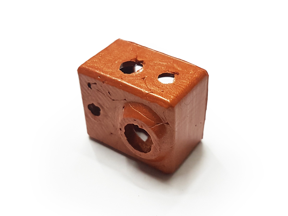
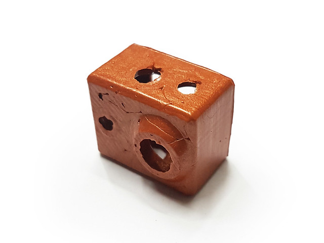
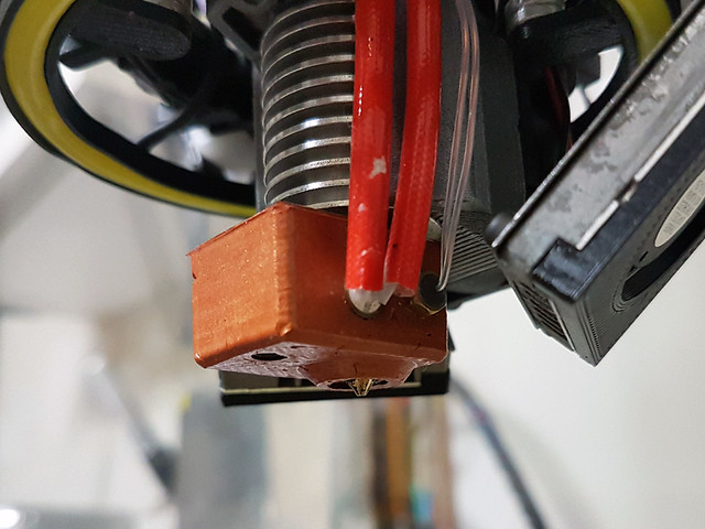
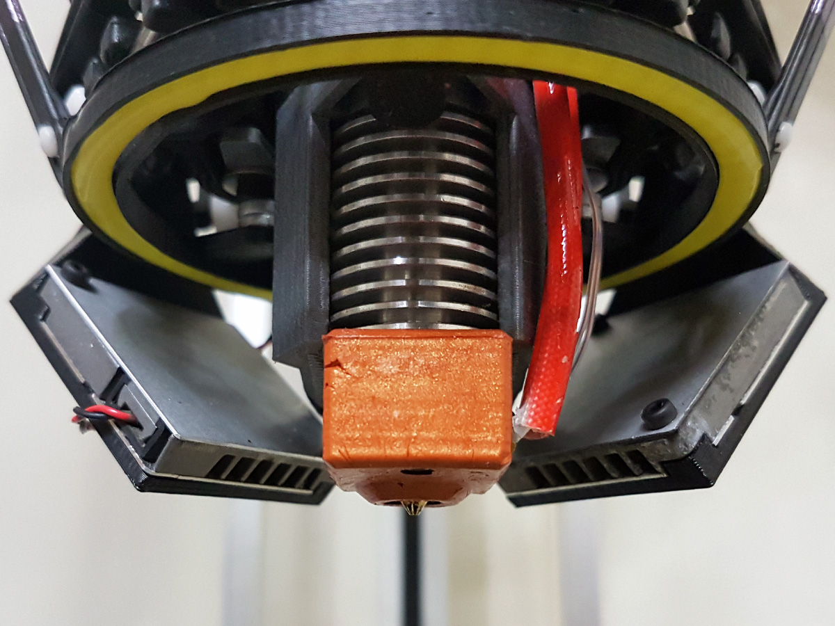
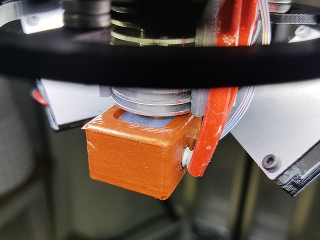
Re: Rostock Max V1.5
https://c2.staticflickr.com/8/7279/2777 ... 8b0f_o.jpg
[img]https://c2.staticflickr.com/8/7279/2777 ... d64a_z.jpg[/img]
https://c2.staticflickr.com/8/7284/2744 ... a3d6_o.jpg
[img]https://c2.staticflickr.com/8/7284/2744 ... 7410_z.jpg[/img]
https://c2.staticflickr.com/8/7329/2805 ... 1d1e_o.jpg
[img]https://c2.staticflickr.com/8/7329/2805 ... c751_z.jpg[/img]
https://c2.staticflickr.com/8/7413/2805 ... db2a_o.jpg
[img]https://c2.staticflickr.com/8/7413/2805 ... c6b8_z.jpg[/img]
https://c2.staticflickr.com/8/7478/2797 ... 92df_o.jpg
[img]https://c2.staticflickr.com/8/7478/2797 ... 284b_z.jpg[/img]
It has been uploaded to thingiverse.
Enjoy!
http://www.thingiverse.com/thing:1655134
Martín S.

Re: Rostock Max V1.5
Amazing build and great work!
SeeMeCNC Rostock Max V2
Makerbot Replicator Gen 5
Makerbot Replicator Gen 5
Re: Rostock Max V1.5
You should design one of those for the stock hot end. 
g.
g.
Delta Power!
Defeat the Cartesian Agenda!
http://www.f15sim.com - 80-0007, The only one of its kind.
http://geneb.simpits.org - Technical and Simulator Projects
Defeat the Cartesian Agenda!
http://www.f15sim.com - 80-0007, The only one of its kind.
http://geneb.simpits.org - Technical and Simulator Projects
Re: Rostock Max V1.5
Thanks for detailing the process. Very helpful! It turned out fantastic.
Rostock MAX V2 with trick trucks, cf arms, prometheus hot end, nimble extruder, berdAir cooling.
Cura slicer, Duet Wifi, iMac
Cura slicer, Duet Wifi, iMac
-
Tincho85
- Printmaster!
- Posts: 659
- Joined: Sun Nov 03, 2013 12:27 pm
- Location: Buenos Aires, Argentina
Re: Rostock Max V1.5
Thanks guys!
Gene send me the STEP files and would gladly make it, or send me one... it's on you
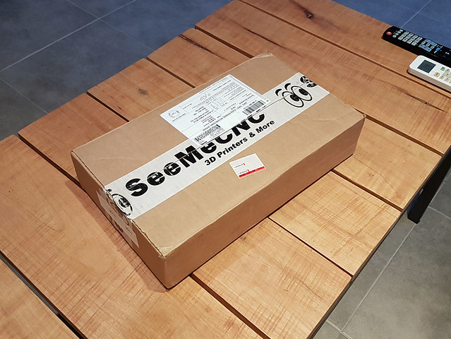
Every time I see this logo, I feel like a little kid when opening a Christmas present.
[img]https://c1.staticflickr.com/9/8821/2865 ... ec66_z.jpg[/img]
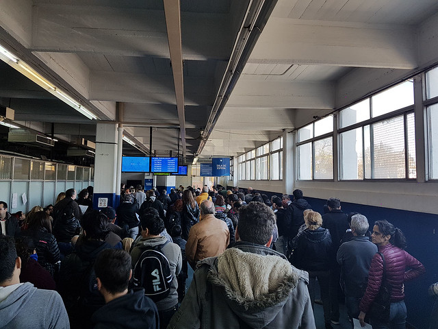
Maybe it's not only because of my nerdy side but because of the gratification it was after this... 3 hours in line at the customs office to retrieve my package. Customs restrictions are kinda hard at the moment.
Not even the smallest package is delivered, you must go there and follow the herd. Supposedly this restriction will end by the end of the month, but here you never now. Time will tell.
[img]https://c1.staticflickr.com/9/8094/2894 ... b397_z.jpg[/img]
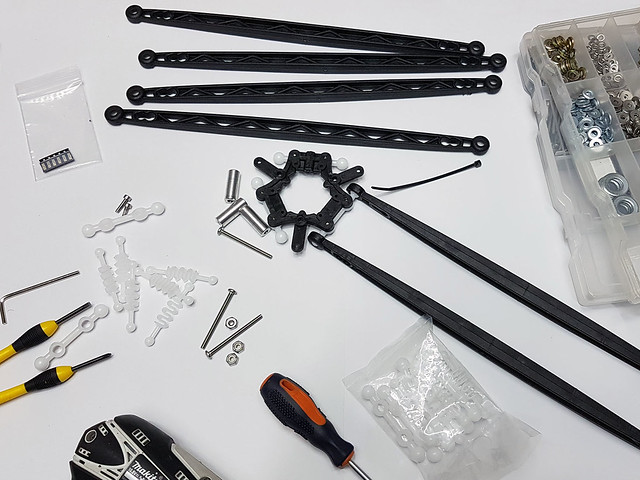
It was so tedious, but that's ok now, I'm finally changing the heavily used u-joint style platform. The Ball-Cup update is in my hands and I'm staying home tonight just to start printing the adapters for the carriages.
I never thought that 3d printing would do that to me lol
[img]https://c1.staticflickr.com/9/8174/2894 ... 29fa_z.jpg[/img]
Wish you all an excellent weekend.
Gene send me the STEP files and would gladly make it, or send me one... it's on you
Every time I see this logo, I feel like a little kid when opening a Christmas present.
[img]https://c1.staticflickr.com/9/8821/2865 ... ec66_z.jpg[/img]
Maybe it's not only because of my nerdy side but because of the gratification it was after this... 3 hours in line at the customs office to retrieve my package. Customs restrictions are kinda hard at the moment.
Not even the smallest package is delivered, you must go there and follow the herd. Supposedly this restriction will end by the end of the month, but here you never now. Time will tell.
[img]https://c1.staticflickr.com/9/8094/2894 ... b397_z.jpg[/img]
It was so tedious, but that's ok now, I'm finally changing the heavily used u-joint style platform. The Ball-Cup update is in my hands and I'm staying home tonight just to start printing the adapters for the carriages.
I never thought that 3d printing would do that to me lol
[img]https://c1.staticflickr.com/9/8174/2894 ... 29fa_z.jpg[/img]
Wish you all an excellent weekend.
Martín S.