Rostock Max V1.5

Start your own build thread so others can see how it's going, and even help out!
User avatar
Tincho85
Printmaster!
Posts: 659
Joined: Sun Nov 03, 2013 12:27 pm
Location: Buenos Aires, Argentina

Rostock Max V1.5

Post by Tincho85 »

A LOT OF PICTURES. LET IT LOAD.

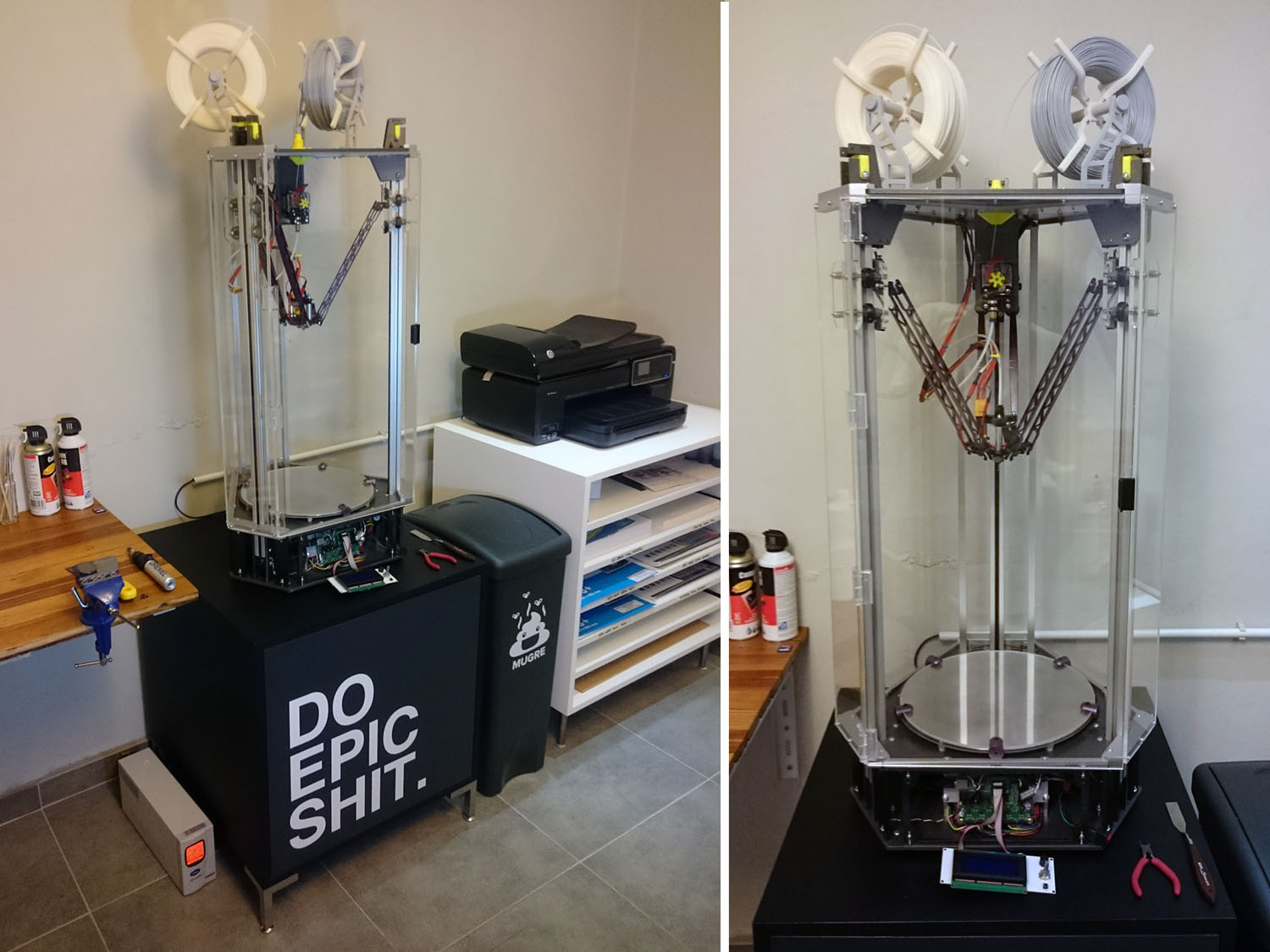
I bought a Rostock Max V1 back in 2013 and I love it! But when I started printing, there were some upgrades and changes I wanted to do. Some could have been done without changing the entire printer, but I'm a fan of sharp edges and I wanted to customize it a little.

I've wanted to share the skin/upgrade of my Rostock for quite some time, so here it is, hope you all enjoy the building process as much as I did.
The printer is running great atm, the pictures were taken a few months ago.

Right now I'm designing a heated chamber to fight warping of big prints.


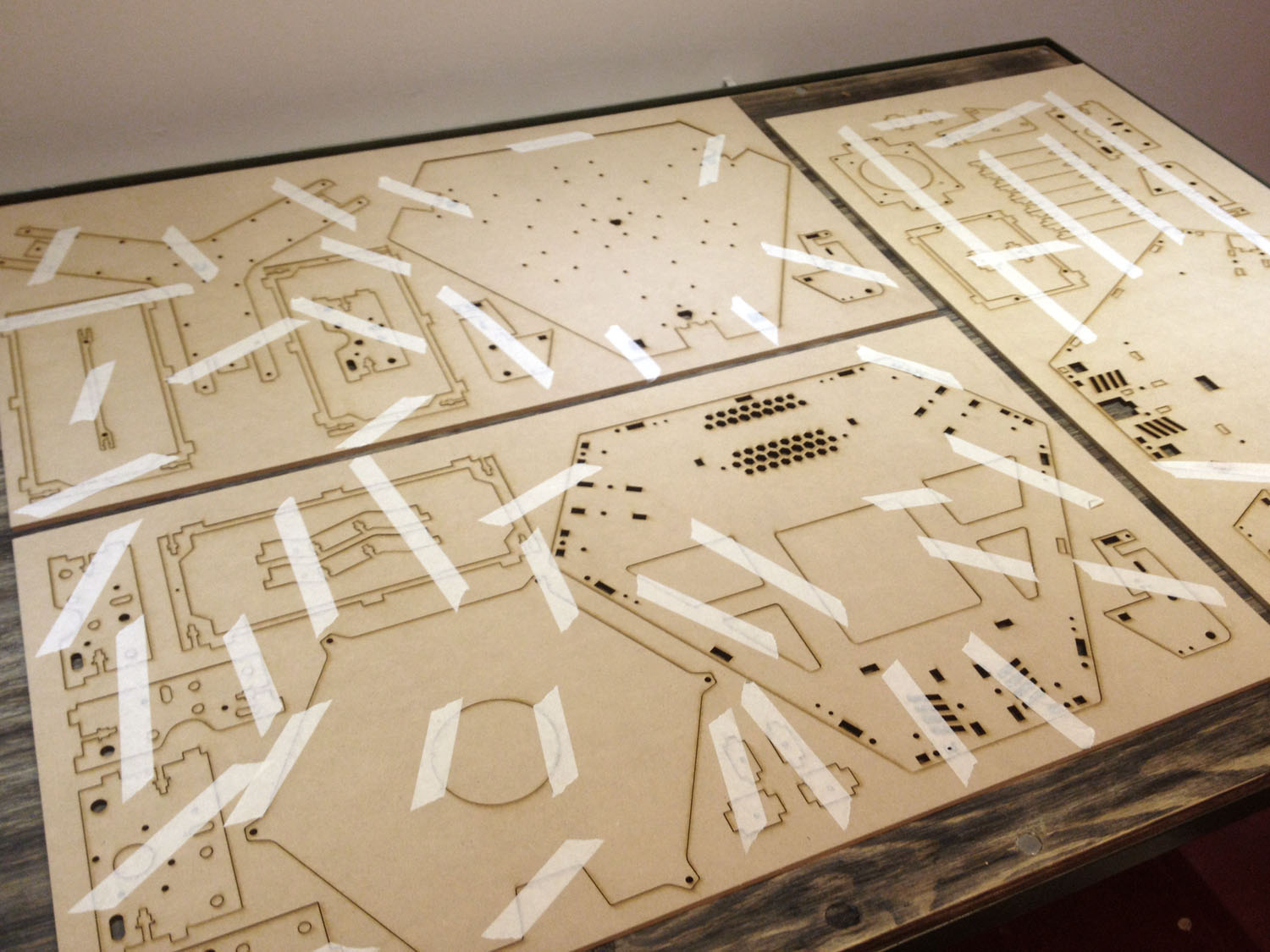
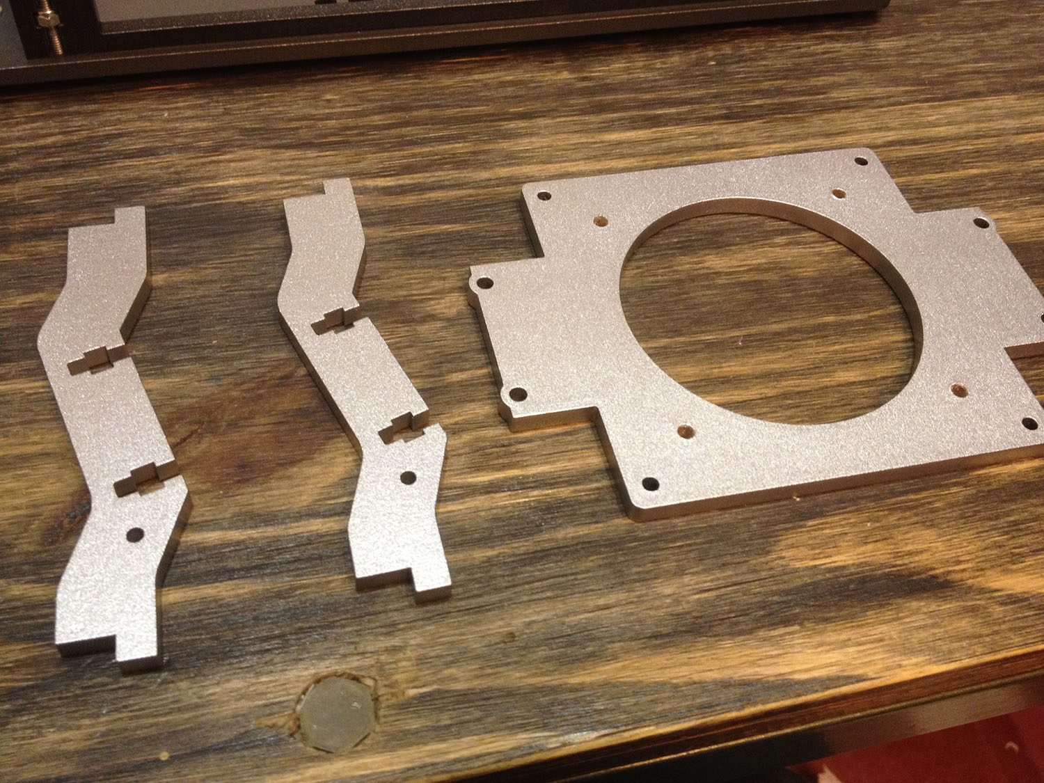
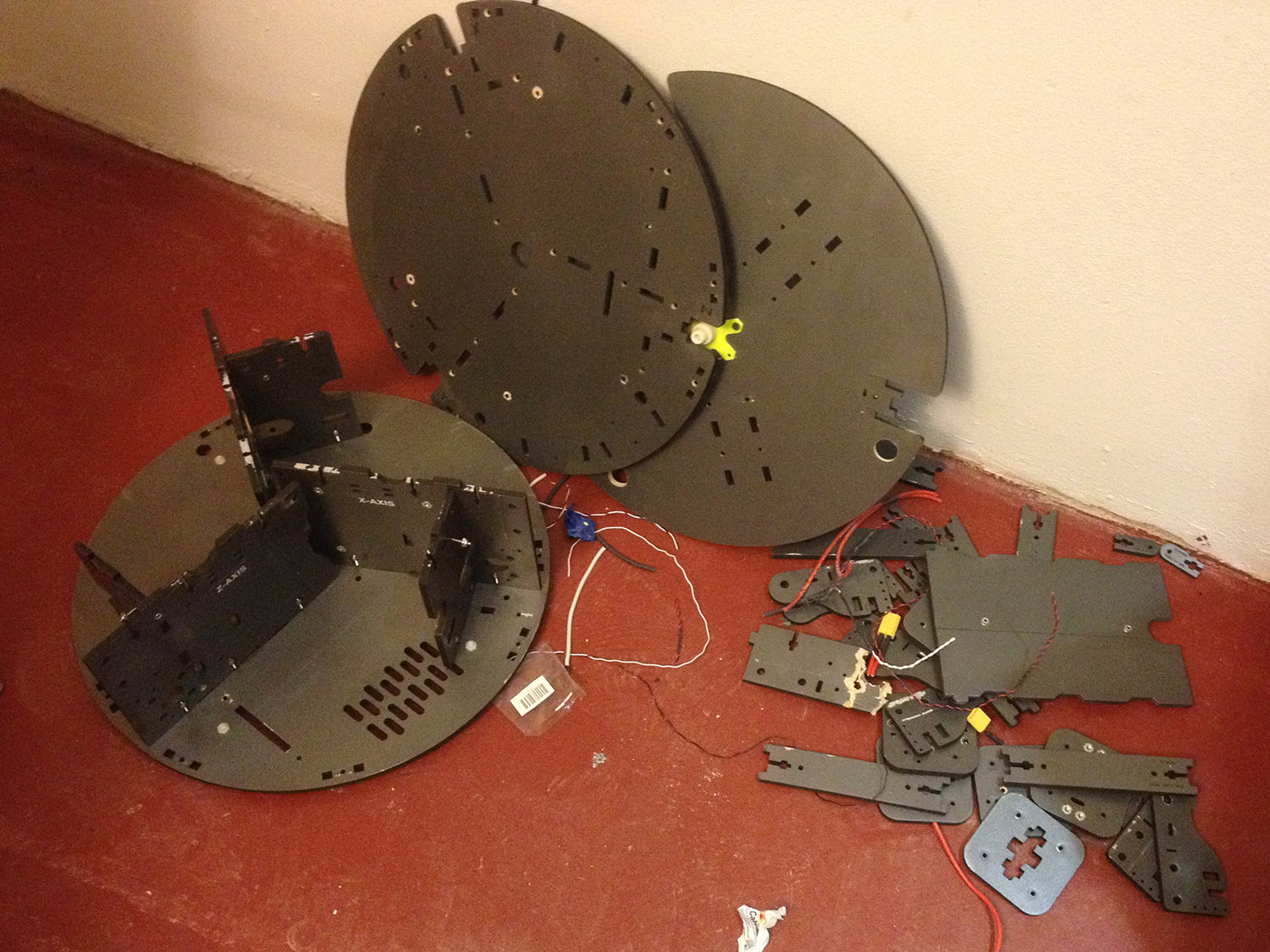
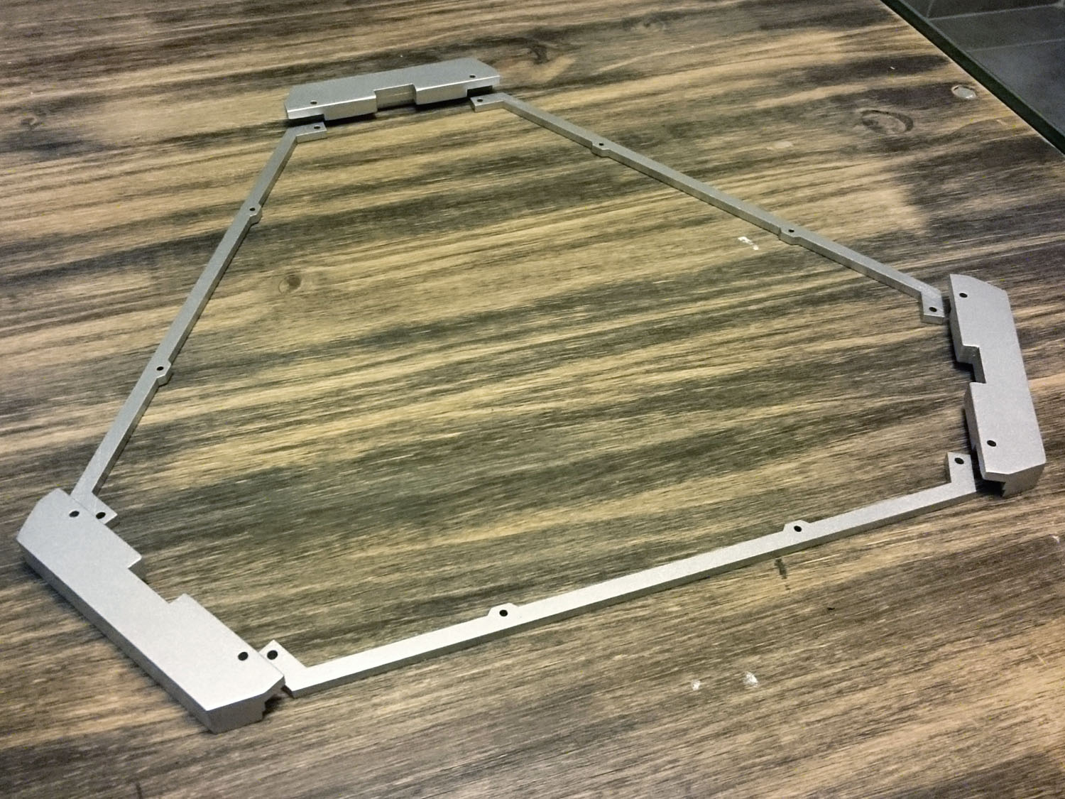
All the parts laser cutted. I've used 5.5mm MDF sheets. I choose to cut them first, so when I paint them I can avoid the burnt edges.
Todas las partes cortadas por laser. use placas de MDF de 5.5mm. Preferi cortarlas primero, asi cuando las pinto puedo eliminar el canto quemado.
[img]https://farm9.staticflickr.com/8638/163 ... b1bc_o.jpg[/img]


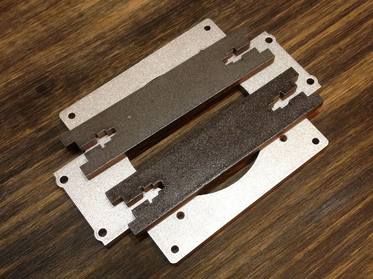
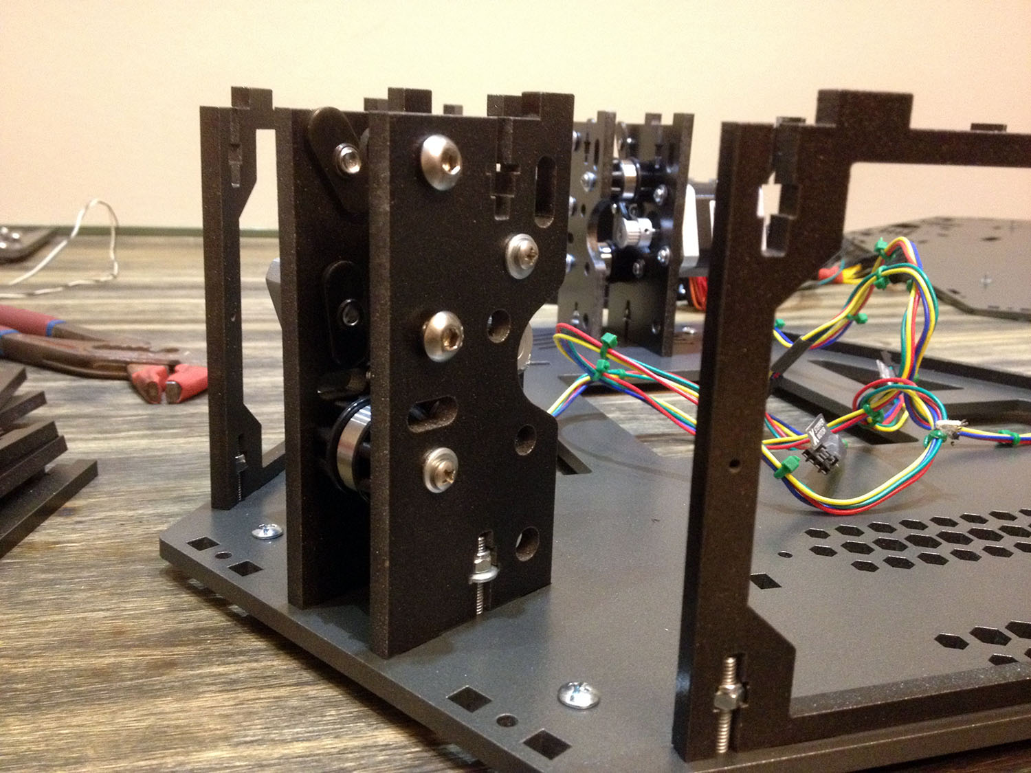
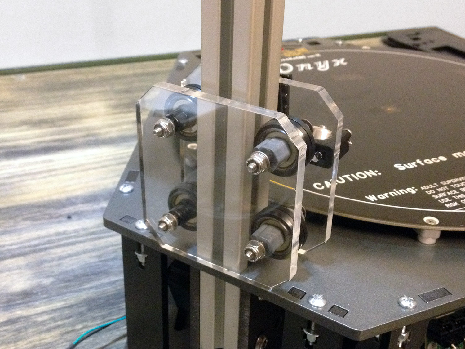
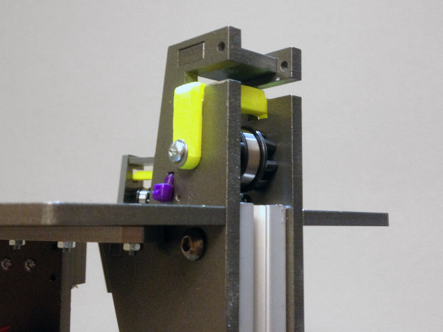
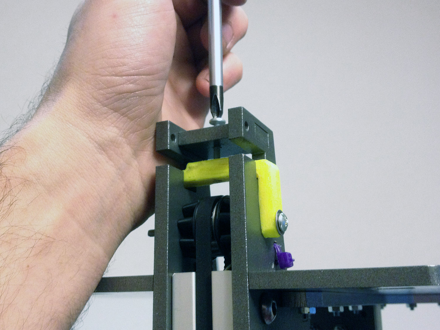
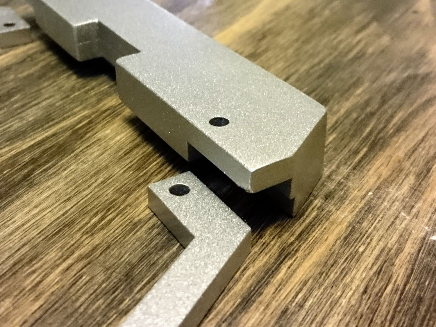
Checking that everything fits.
Si señor! todo calza perfecto.
[img]https://farm8.staticflickr.com/7374/165 ... 2ddc_o.jpg[/img]
[img]https://farm8.staticflickr.com/7394/163 ... 970c_o.jpg[/img]


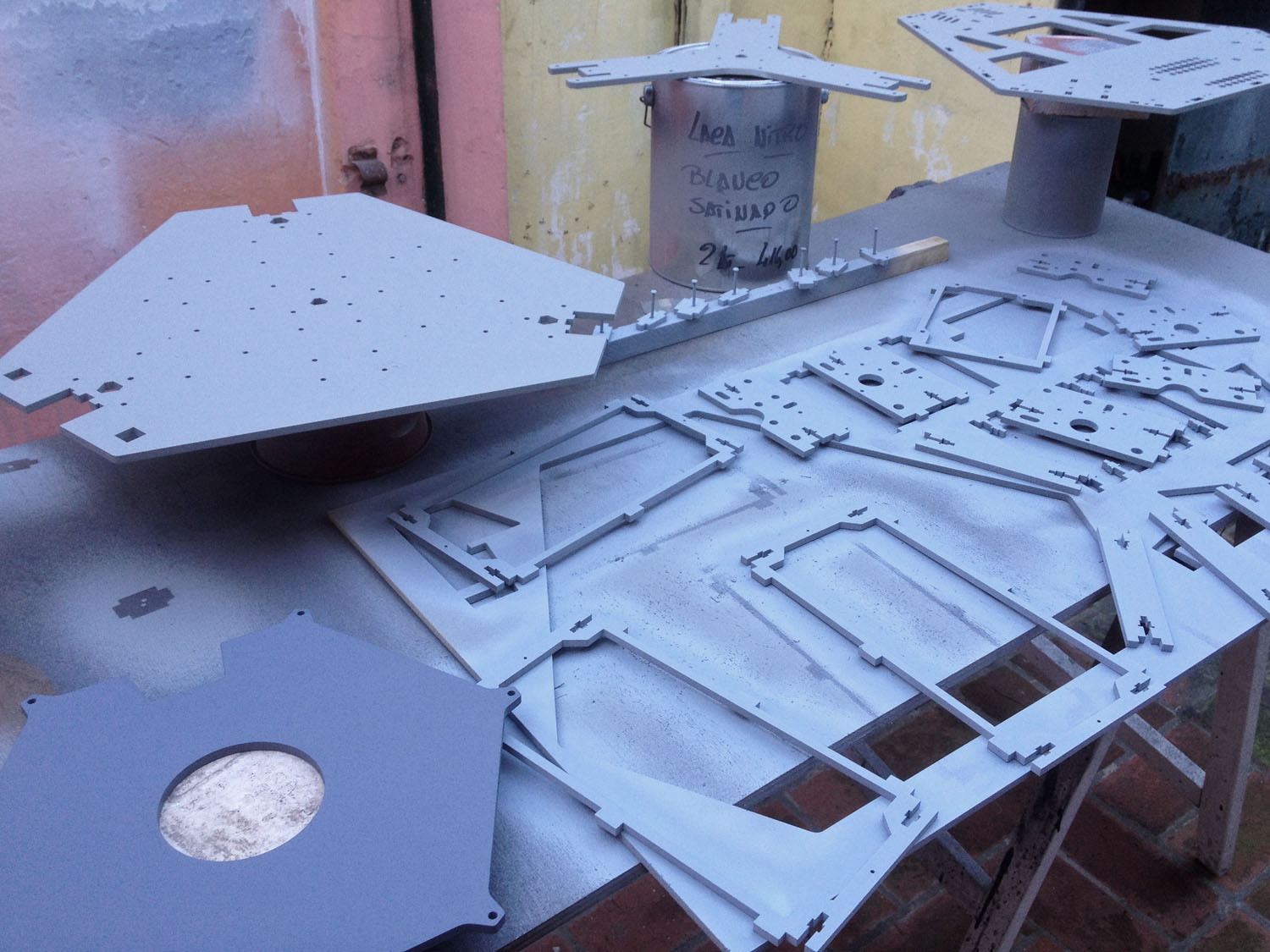
The first layer of Primer.
Aplicando la primer capa de Primer
[img]https://farm8.staticflickr.com/7453/159 ... 407b_o.jpg[/img]


The 3 colors I used for the printer. They all have a metallic finish.
Use 3 colores diferentes, todos dentro del tono de los grises metalizados
[img]https://farm8.staticflickr.com/7457/163 ... 140c_o.jpg[/img]
[img]https://farm9.staticflickr.com/8624/163 ... c63b_o.jpg[/img]


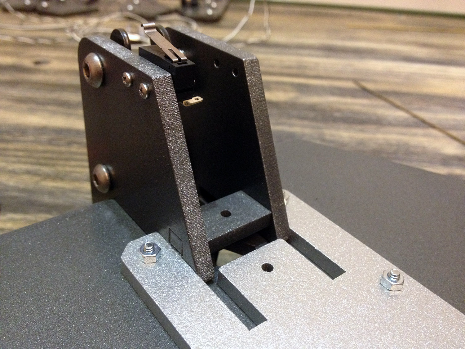
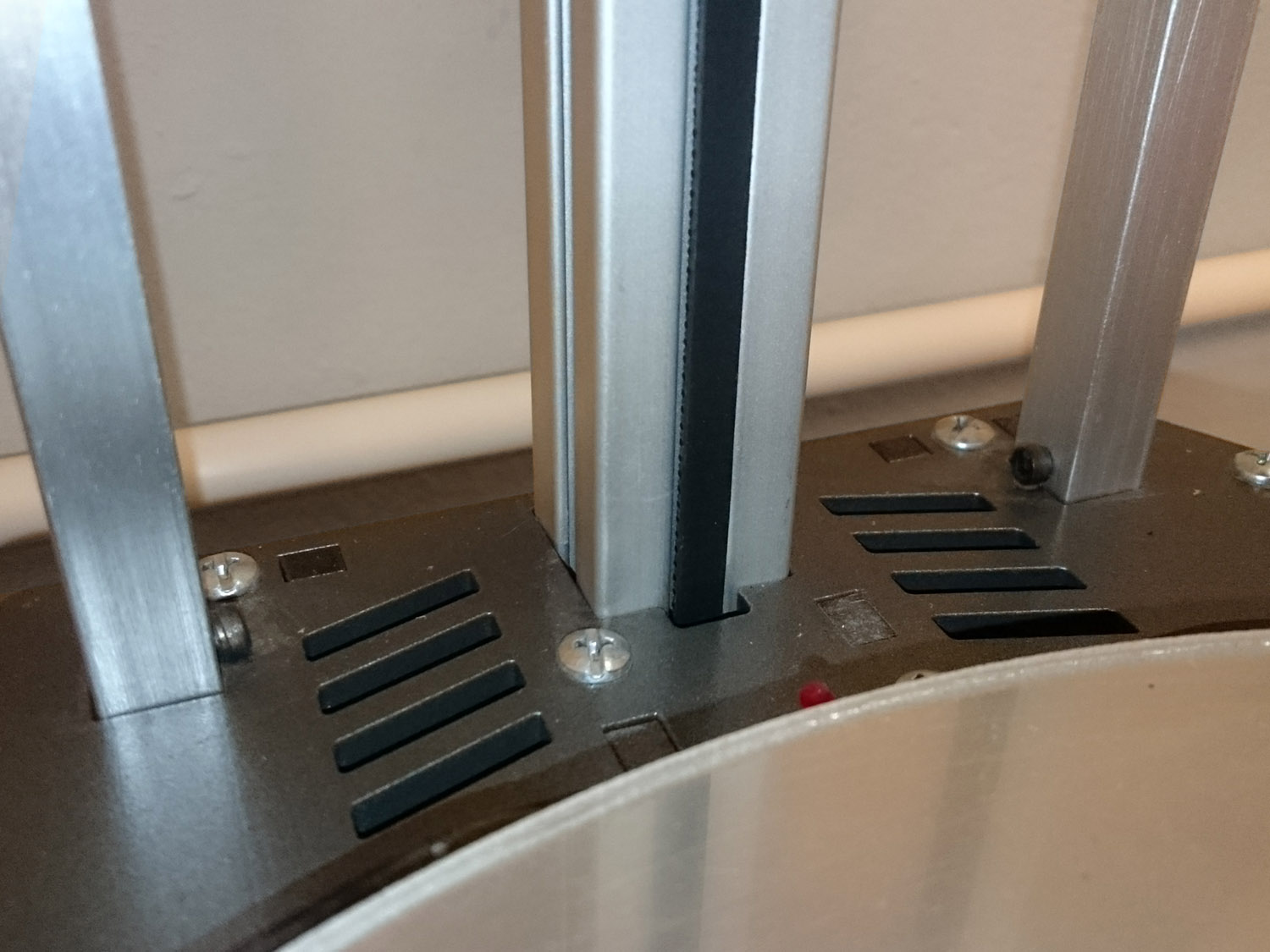
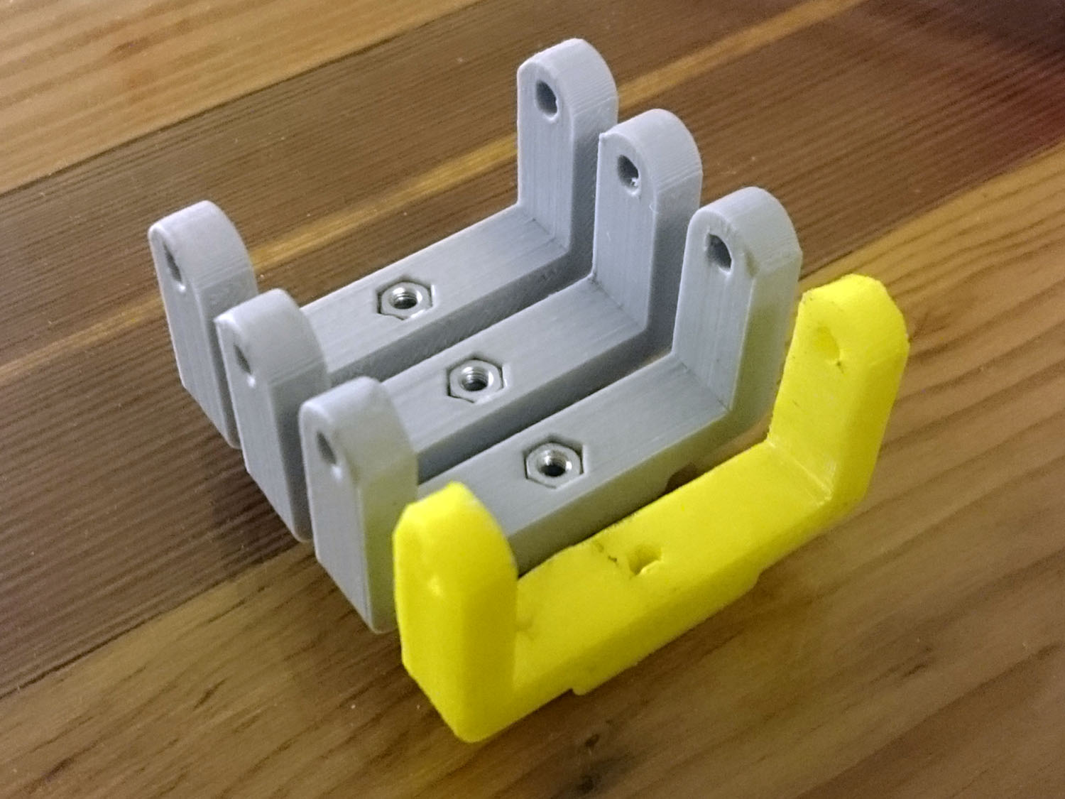
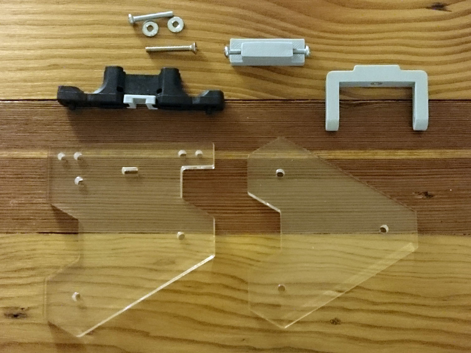
I've used a combination of acrylic and cork for the foot assemblies.
Para las patas que soportan la maquina, utilize una combinacion de corcho y acrilico.
[img]https://farm8.staticflickr.com/7332/163 ... 0bc5_o.jpg[/img]
[img]https://farm8.staticflickr.com/7442/165 ... e8ed_o.jpg[/img]


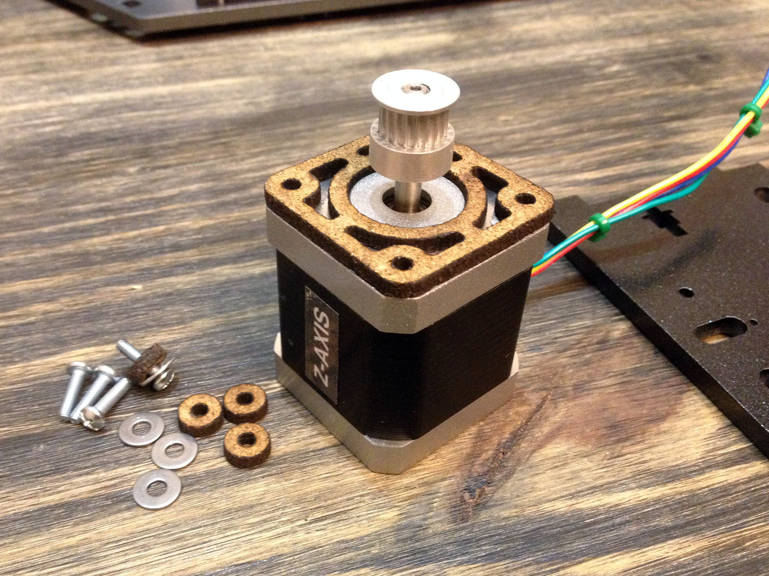
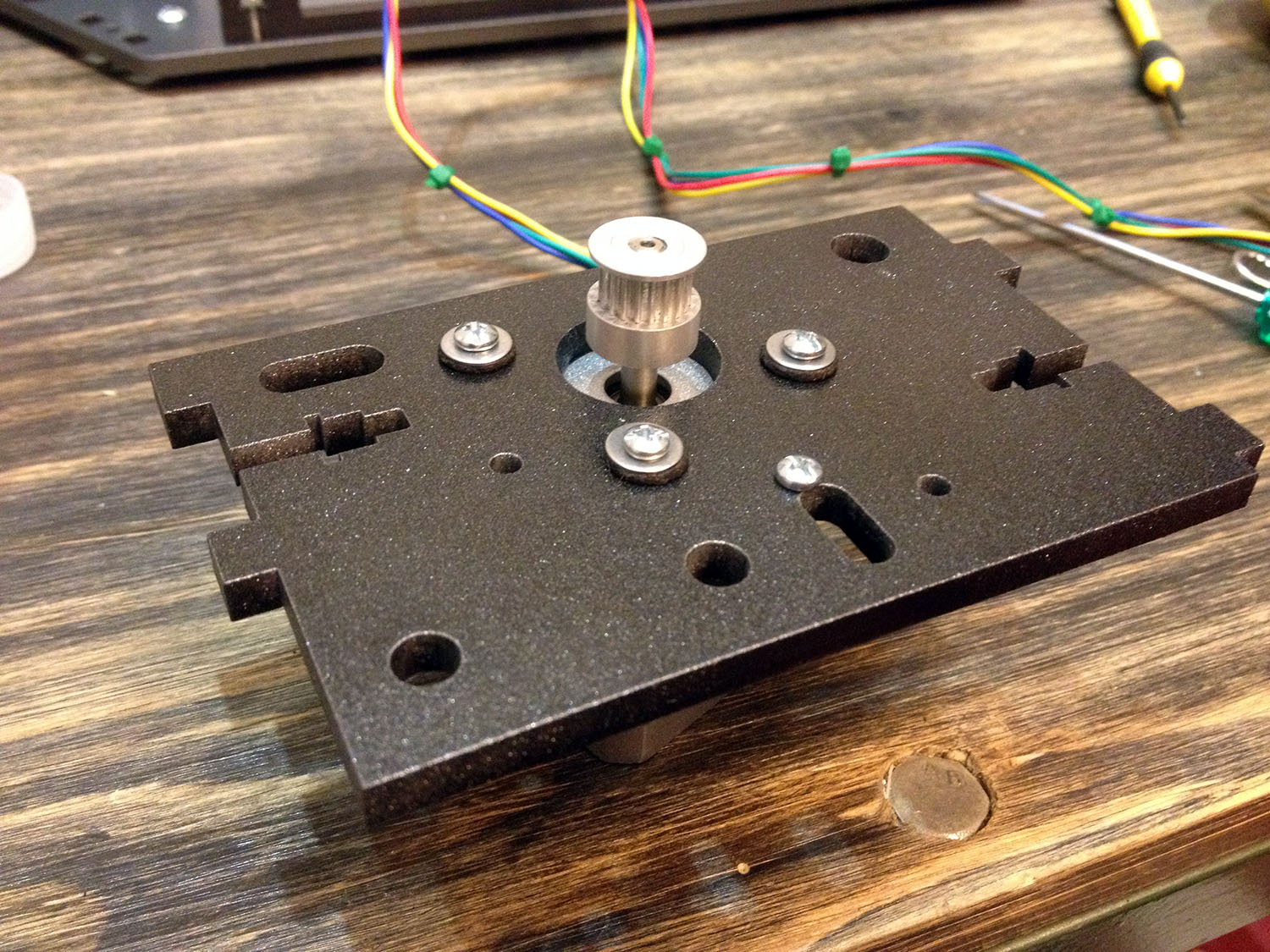
Cork stepper dampers... these shoud be included in the pack or at least a note in the manual.
It's a huge change regarding noise.
Dampers de corcho, hacen una terrible diferencia en cuanto al ruido. El mejor upgrade que le hice a mi Rostock
[img]https://farm9.staticflickr.com/8618/165 ... 05d1_o.jpg[/img]
[img]https://farm8.staticflickr.com/7362/159 ... 283e_o.jpg[/img]


All good :)
[img]https://farm8.staticflickr.com/7372/163 ... 5687_o.jpg[/img]
[img]https://farm8.staticflickr.com/7372/165 ... 50ee_o.jpg[/img]


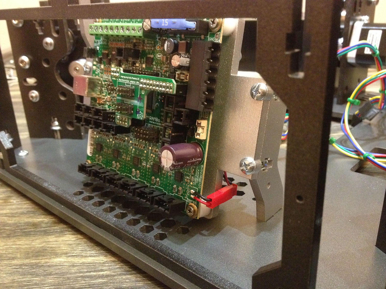
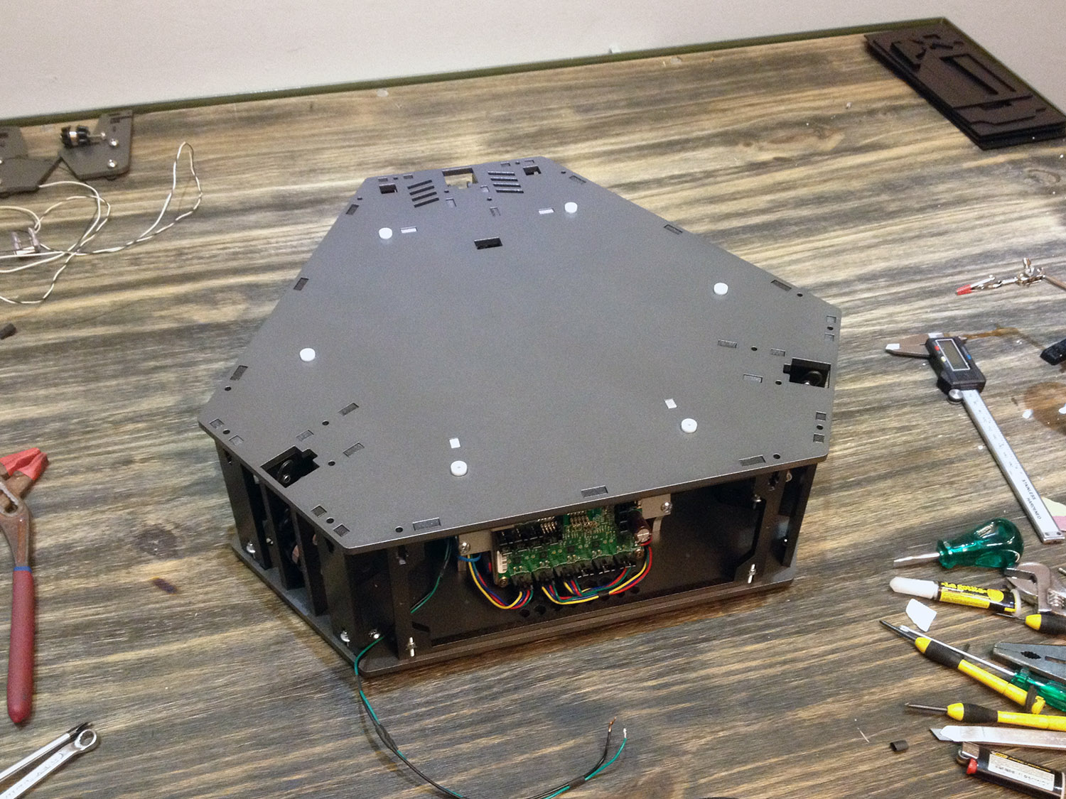
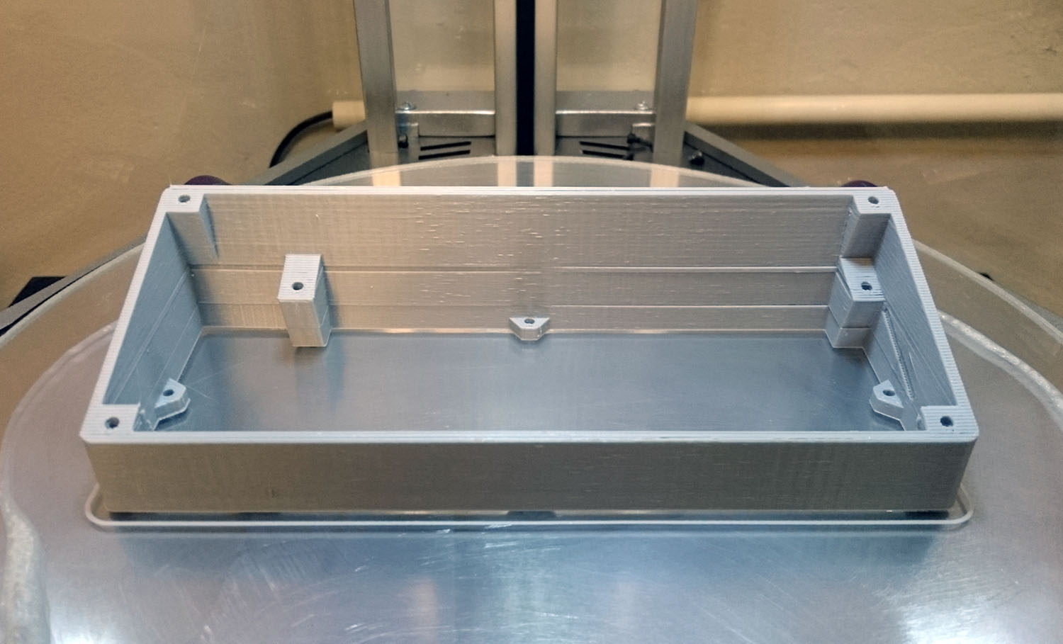
The supports for the Rambo board.
Instalando los sopotes para el controlador Rambo.
[img]https://farm8.staticflickr.com/7412/165 ... 00a0_o.jpg[/img]
[img]https://farm9.staticflickr.com/8653/159 ... 25af_o.jpg[/img]


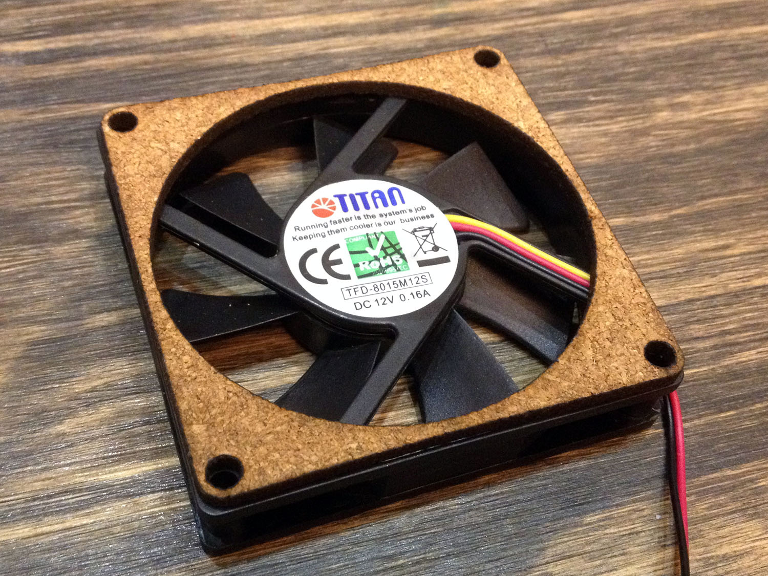
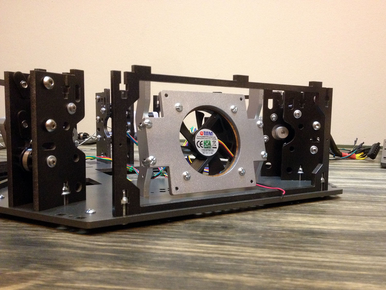
Yes, I know it's probably too much, but It wont hurt some cork for the big board fan.
Ehh... creo que es mucho, pero un poco de corcho para el ventilador del Rambo no creo que le haga mal.
[img]https://farm9.staticflickr.com/8637/165 ... 3279_o.jpg[/img]
[img]https://farm8.staticflickr.com/7344/159 ... dd2f_o.jpg[/img]
[img]https://farm9.staticflickr.com/8631/159 ... 43f7_o.jpg[/img]


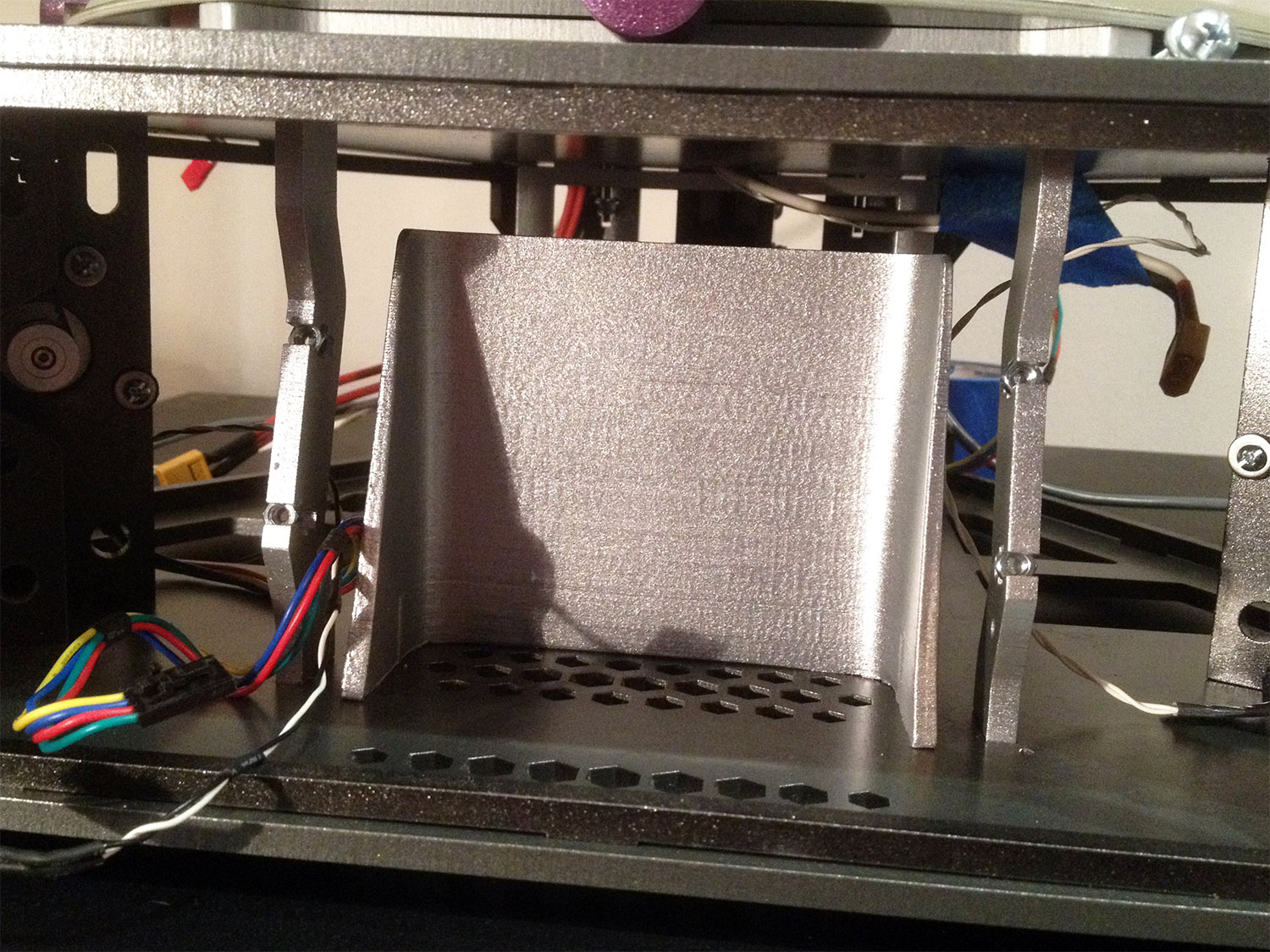
The fan from the PSU goes directly to the board, so I've printed a protective wall to guide the air flow.
La salida de la fuente le da justo a donde toma aire el ventilador del Rambo, asi que imprimi una pared protectora para guiar el flujo de aire.
[img]https://farm9.staticflickr.com/8609/165 ... 6d51_o.jpg[/img]
[img]https://farm8.staticflickr.com/7285/165 ... a514_o.jpg[/img]
[img]https://farm8.staticflickr.com/7324/159 ... 5627_o.jpg[/img]


Time to close this! :o
[img]https://farm8.staticflickr.com/7340/159 ... bf89_o.jpg[/img]


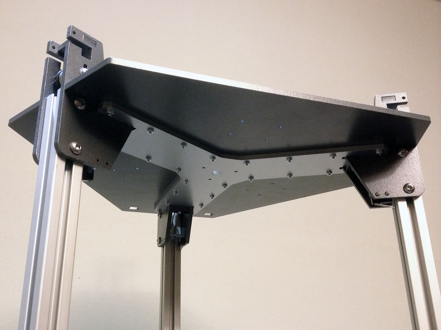
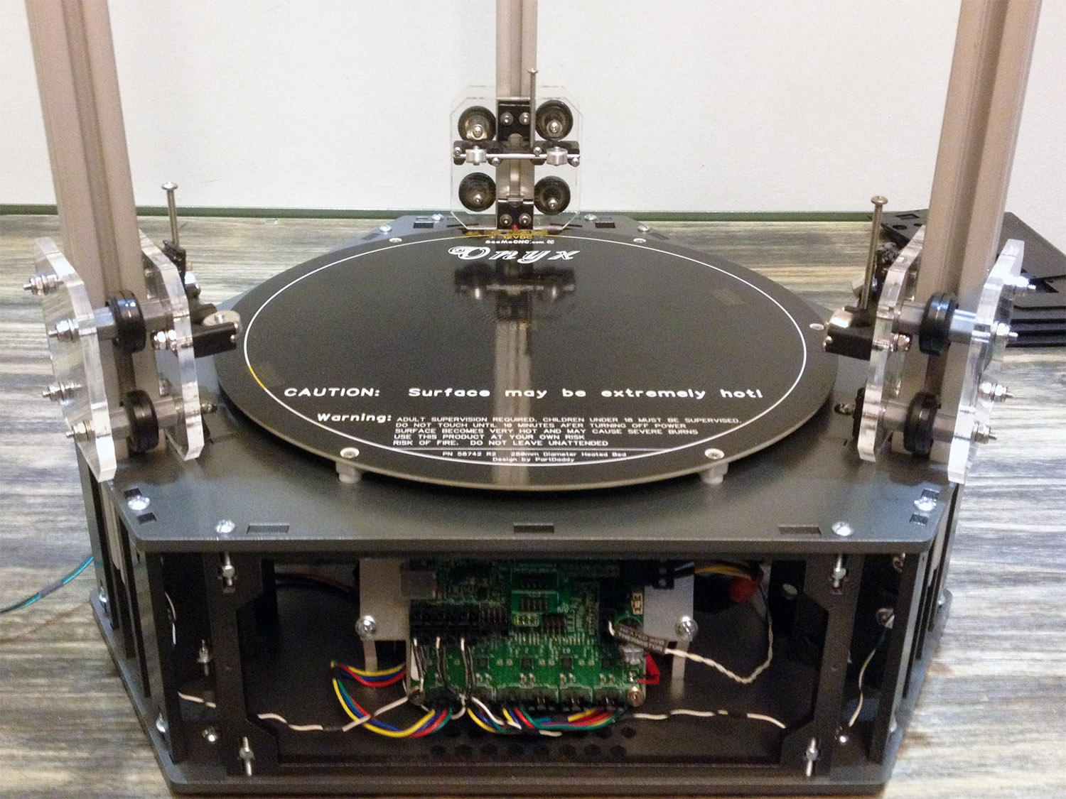
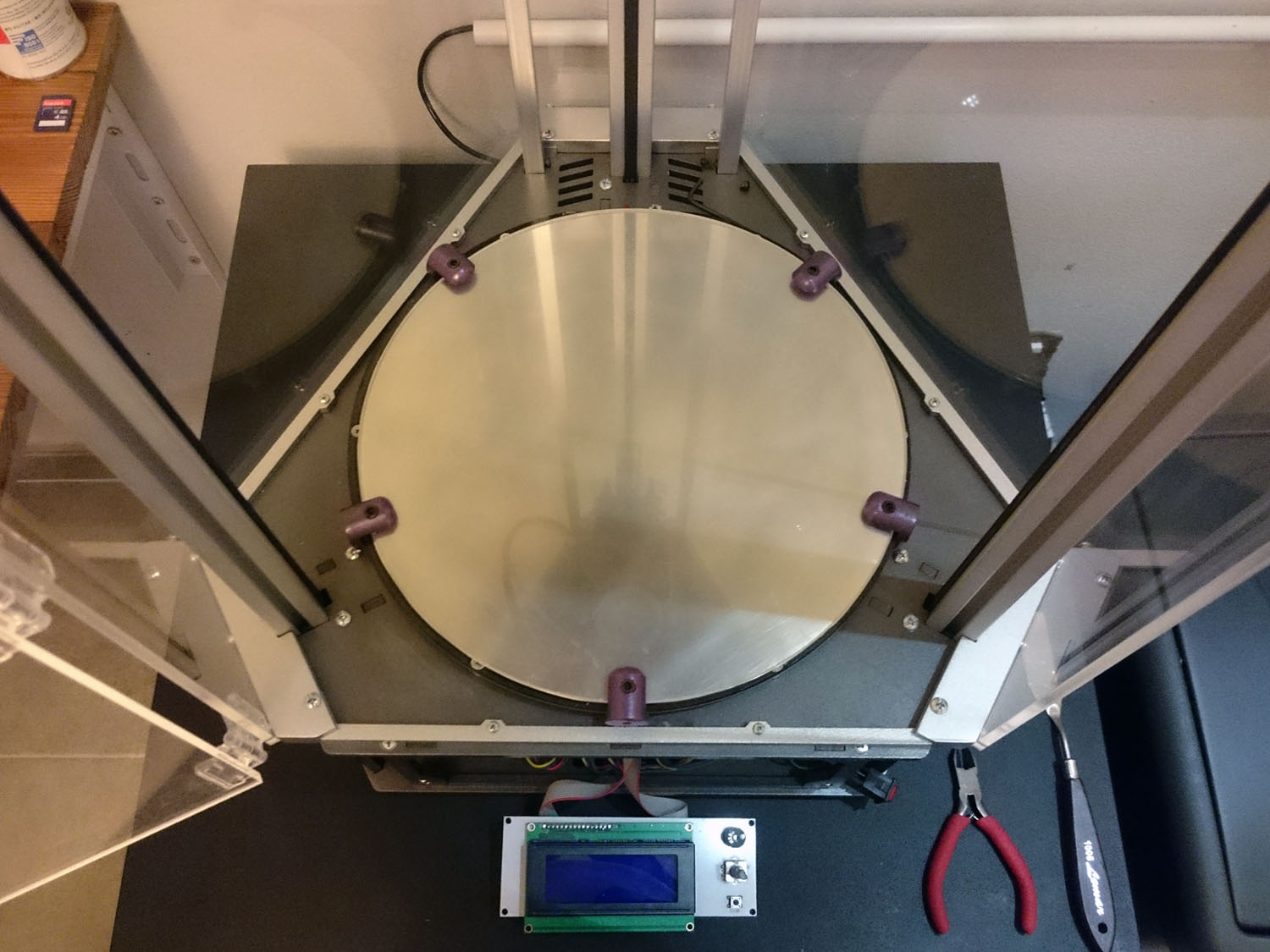
Maybe just a little paranoid, but the heated bed mounting plate was painted using high temp paint.
Utilize pintura resistente a altas temperaturas para el soporte de la heated bed. Otra vez... tal vez es mucho, pero bue!
[img]https://farm8.staticflickr.com/7293/163 ... 6d7e_o.jpg[/img]


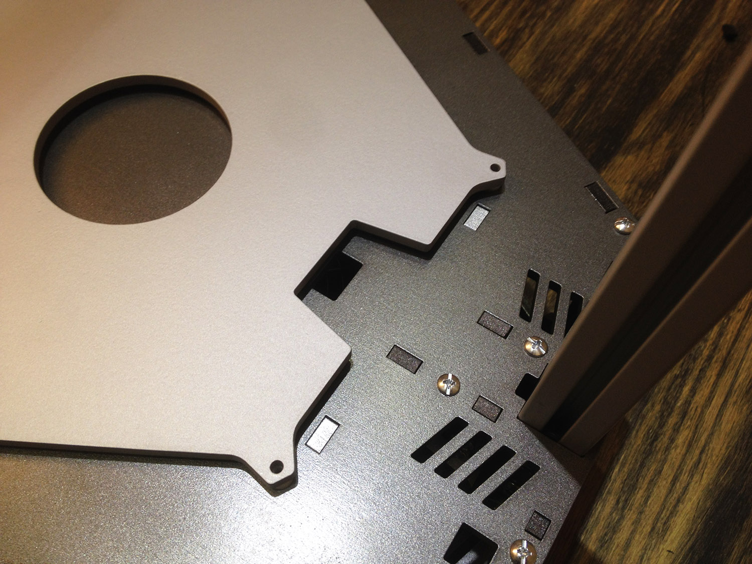
The hole for the heated bed cables.
Por aca pasan los cables de la heated bed.
[img]https://farm8.staticflickr.com/7311/163 ... 027a_o.jpg[/img]


That's all for today. I've more pictures of the process, feel free to visit my Flickr album. https://flic.kr/s/aHsk7U1TmP
I'll continue this post later, when I find the other pics :cry:

Eso es todo por hoy, en los próximos días ire subiendo mas fotos.
Todavía estos trantando de encontrarlas claro, pero en alguna carpeta backup deben estar.
Last edited by Tincho85 on Wed Mar 18, 2015 6:50 pm, edited 2 times in total.
Martín S.
bot
Printmaster!
Posts: 993
Joined: Thu Sep 25, 2014 12:18 am
Location: Vancouver
Contact:

Re: Rostock Max V1.5

Post by bot »

Beautiful!
*not actually a robot
JFettig
Printmaster!
Posts: 824
Joined: Tue Nov 18, 2014 4:39 pm
Location: Minnesota

Re: Rostock Max V1.5

Post by JFettig »

That is one mean looking machine - its what the printer should have looked like in my opinion!

You have a nice setup for building a heated chamber with those wide edges, my designed chamber is wide like that and has a similar shape.
User avatar
Eaglezsoar
ULTIMATE 3D JEDI
Posts: 7185
Joined: Sun Apr 01, 2012 5:26 pm

Re: Rostock Max V1.5

Post by Eaglezsoar »

Excellent work! That is a machine to be proud of, those many hours of work has certainly paid off and I am anxious to see it printing.
User avatar
Tincho85
Printmaster!
Posts: 659
Joined: Sun Nov 03, 2013 12:27 pm
Location: Buenos Aires, Argentina

Re: Rostock Max V1.5

Post by Tincho85 »

Thanks guys, I really appreciate it. :D


For the top section base plate, I've used a combination of 2 MDF sheets. I liked the look of the V1 but it was too weak and it bended easily.
The "Y" shaped plate works a reinforcement, but with the intention of adding minimal weight.
Para la placa superior utilize 2 placas de MDF. De esta manera logro una superficie fuerte sin sacrificar peso.
[img]https://farm8.staticflickr.com/7303/165 ... bd4f_o.jpg[/img]


The upper tower mount slides all the way to the hole that connects both plates. This way I increase contact area and get a much stronger union.
Los sujetadores de las torres se deslizan hasta el agujer que conecta las 2 placas de MDF.
De esta manera se incrementa la superficie de contacto y se logra una union mucho mas fuerte.

[img]https://farm8.staticflickr.com/7423/163 ... fb10_o.jpg[/img]
[img]https://farm8.staticflickr.com/7358/159 ... 63e5_o.jpg[/img]
[img]https://farm9.staticflickr.com/8593/165 ... 56f7_o.jpg[/img]
[img]https://farm8.staticflickr.com/7423/163 ... 8403_o.jpg[/img]


I made the cheapskate carriages using acrylic, because the look cooler and to help with the regulation of the eccentric rollers.
I shoud have changed the position of the U-Joint carriage base to to gain additional build height but well... I forgot it
Los cheapskate carriages fueron realizados en acrilico tranparente para una mas facil regulacion de los rollers.
[img]https://farm9.staticflickr.com/8679/163 ... 8c16_o.jpg[/img]
[img]https://farm8.staticflickr.com/7459/163 ... 83a8_o.jpg[/img]
[img]https://farm9.staticflickr.com/8594/163 ... d7ce_o.jpg[/img]

At the moment I have the new U-Joint spring clips and the injection molded U-Joints. They work great!
[img]https://farm8.staticflickr.com/7456/165 ... 48e0_o.jpg[/img]


A little help to adjust the belt tension. It uses a single bolt.
Una pequeña ayuda para ajustar la tension de las correas. Utiliza un unico tornillo.
[img]https://farm8.staticflickr.com/7328/159 ... 56bb_o.jpg[/img]
[img]https://farm8.staticflickr.com/7384/163 ... d0d9_o.jpg[/img]
[img]https://farm8.staticflickr.com/7369/165 ... 89ed_o.jpg[/img]
Last edited by Tincho85 on Mon Feb 16, 2015 5:59 pm, edited 2 times in total.
Martín S.
User avatar
Tincho85
Printmaster!
Posts: 659
Joined: Sun Nov 03, 2013 12:27 pm
Location: Buenos Aires, Argentina

Re: Rostock Max V1.5

Post by Tincho85 »

This is the mount for the bowden E3D v5. It was made using black acrylic. It could be 3d printed though.
Diseñe estas piezas para sostener el E3d v5 hot end. Fue realizado en acrilico, pero tranquilamente puede imprimirse en 3d.
[img]https://farm9.staticflickr.com/8565/163 ... 62e3_o.jpg[/img]
[img]https://farm8.staticflickr.com/7283/163 ... ac60_o.jpg[/img]
[img]https://farm8.staticflickr.com/7286/165 ... 69b0_o.jpg[/img]
[img]https://farm9.staticflickr.com/8625/163 ... 7c2f_o.jpg[/img]
[img]https://farm8.staticflickr.com/7349/163 ... 0d8e_o.jpg[/img]
[img]https://farm9.staticflickr.com/8664/165 ... aacf_o.jpg[/img]


2 aluminum hollow bars connect the the top plate with the rambo section.
2 barras huecas de aluminio conectan la parte superior de la impresora con el sector electrico.
[img]https://farm8.staticflickr.com/7366/165 ... fd23_o.jpg[/img]
[img]https://farm9.staticflickr.com/8669/163 ... ebe3_o.jpg[/img]

I've cutted an M3 bolt so that it prevents the bars from moving.
Corte un tornillo M3 para prevenir que las barras se muevan.
[img]https://farm8.staticflickr.com/7314/159 ... d6a1_o.jpg[/img]
[img]https://farm8.staticflickr.com/7415/165 ... c7db_o.jpg[/img]


Woaaaaa.... found this picture a few min ago LOL
[img]https://farm9.staticflickr.com/8679/163 ... e5ae_o.jpg[/img]


EDIT: Here it's the file for the heat sink mount.
http://www.thingiverse.com/thing:685582
Martín S.
User avatar
Tincho85
Printmaster!
Posts: 659
Joined: Sun Nov 03, 2013 12:27 pm
Location: Buenos Aires, Argentina

Led Light Ring!

Post by Tincho85 »

Hi guys, it's been long since the last update. I've finished the heated chamber, and the change with big prints it's incredible (at least with ABS, I don't use PLA).
Will post the process later today.

I've some pictures of the led ring, it may give some ideas for installing them.


I placed the led ring below the effector platform, and with a marker made some dots so I know where to put the magnets.
Puse el anillo de led debajo de la plataforma y con un rotulador marque los puntos en donde deben ir los imanes.
[img]https://farm9.staticflickr.com/8619/167 ... 211c_o.jpg[/img]


Then I sanded the magnets and glued them to the ring using cyanoacrylate (think it's called super glue in North America).
Shrink tube and JST connectors for a quick disconnect option.
Lijar un poco los imanes y luego pegarlos con cyano. Termocontraible y conectores JST para una rapida desconeccion.
[img]https://farm8.staticflickr.com/7285/167 ... 64f4_o.jpg[/img]


Voilà!
[img]https://farm8.staticflickr.com/7601/165 ... 463f_o.jpg[/img]
Martín S.
User avatar
Tincho85
Printmaster!
Posts: 659
Joined: Sun Nov 03, 2013 12:27 pm
Location: Buenos Aires, Argentina

Enclosure

Post by Tincho85 »

The design was based on Raymonds heated chamber:
http://blog.rymnd.com/articles/rostock-upgrades/
http://forum.seemecnc.com/viewtopic.php?f=35&t=5695
I didn't add an IR lamp or any kind of heater so there is no need to move the extruder, but the changes when printing where still amazing.
Now I can turn the air conditioner! :D


Made a frame that fits both the bottom and top of the Rostock using M3 screws. At first I thought of printing them, but laser cutted MDF turned out to be cheaper.
El marco lo hice en MDF porque salía mas barato que imprimirlo. Las barras que conectan las 3 esquinas funcionan como juntas para evitar que salga/entre aire.
[img]https://farm8.staticflickr.com/7605/165 ... c0b9_o.jpg[/img]
[img]https://farm9.staticflickr.com/8667/161 ... 5127_o.jpg[/img]


Oh boy... here I was really scared. I wanted to use plastic hinges, they look nice and don't requiere screws... but it was very tricky to install them.
To join 2 pieces of acrylic it requieres acetone, toluene or chloroform. They solder together (It doesn't work like a glue). Hold the hinge using a clamp and with a syringe fill the gap. Let it rest for 3 hours.
NOTE: if a drop of acetone touches the acrylic just let it air dry.
Como putie acá! Quería usar bisagras de acrílico, porque quedan geniales y no usan tornillería. Pero fue muy difícil instalarlas. Para pegarlas hay que usar acetona, cloroformo o tolueno. En realidad no se pegan sino que se sueldan. Sujetar la bisara usando un sargento y con una jeringa llenar el vínculo. Luego dejarlo descansar por al menos 3 horas.
[img]https://farm8.staticflickr.com/7624/167 ... c094_o.jpg[/img]
[img]https://farm8.staticflickr.com/7622/161 ... 8031_o.jpg[/img]
[img]https://farm8.staticflickr.com/7601/161 ... d1fb_o.jpg[/img]


After installing the 4 hinges I removed that side and solder the door.
Let it rest for 24 hours just to be sure the bond was strong.
Después de pegar las 4 bisagras, remover ese lateral y pegar la puerta. Me ayude de unas pesas para poder pegar la puerta, ya que no podía utilizar los sargentos.
Dejar secar todo mínimo 24 horas. El peso de la puerta podría despegarla si se la coloca antes.

[img]https://farm8.staticflickr.com/7618/165 ... 53c6_o.jpg[/img]


And this is how it is today. Hope you like it.
Así es como está ahora. Espero que les guste.
[img]https://farm8.staticflickr.com/7597/167 ... 6a32_o.jpg[/img]


I still need to make a box for the LCD controller. :mrgreen:
Martín S.
bot
Printmaster!
Posts: 993
Joined: Thu Sep 25, 2014 12:18 am
Location: Vancouver
Contact:

Re: Rostock Max V1.5

Post by bot »

Epic.

Do you re-spool all your filament onto your custom reels? What's the purpose of that?
*not actually a robot
User avatar
Tincho85
Printmaster!
Posts: 659
Joined: Sun Nov 03, 2013 12:27 pm
Location: Buenos Aires, Argentina

Re: Rostock Max V1.5

Post by Tincho85 »

bot wrote:Epic.

Do you re-spool all your filament onto your custom reels? What's the purpose of that?
God no, that would be too much work :D
The problem is that here in Argentina it's very difficult to buy good filament and I manage to find one that is good and cheap, but it comes without a reel.
So I use this custom reel that doesn't requiere to re-spool it. Hope I make sense.
Martín S.
User avatar
Tincho85
Printmaster!
Posts: 659
Joined: Sun Nov 03, 2013 12:27 pm
Location: Buenos Aires, Argentina

Re: Rostock Max V1.5

Post by Tincho85 »

An image works better, i find it hard to explain myself in English.

[img]https://farm9.staticflickr.com/8727/165 ... 4e98_o.jpg[/img]

Each "Y" is individual so there's no need to re-spool it.
Martín S.
User avatar
teoman
ULTIMATE 3D JEDI
Posts: 1783
Joined: Sat May 24, 2014 5:43 pm

Re: Rostock Max V1.5

Post by teoman »

So you assemble it inside your roll of filament to transform it to a spool right.
When on mobile I am brief and may be perceived as an arsl.
User avatar
Nylocke
ULTIMATE 3D JEDI
Posts: 1421
Joined: Sun Jun 23, 2013 1:43 pm
Location: Iowa

Re: Rostock Max V1.5

Post by Nylocke »

Thats a really nice enclosure.
User avatar
Tincho85
Printmaster!
Posts: 659
Joined: Sun Nov 03, 2013 12:27 pm
Location: Buenos Aires, Argentina

Re: Rostock Max V1.5

Post by Tincho85 »

teoman wrote:So you assemble it inside your roll of filament to transform it to a spool right.
Yes sir.
Nylocke wrote:Thats a really nice enclosure.
Thanks for the kind words.


I've just finished printing the LCD panel mount and it came out a bit strange.
Looking it from the back it looks good.
[img]https://farm8.staticflickr.com/7613/161 ... 2978_o.jpg[/img]

But from the inside it seems that one layer moved. In the center is ok, but close to the edges moved to opposite sides.
[img]https://farm9.staticflickr.com/8638/165 ... 84fc_o.jpg[/img]

Close-up
[img]https://farm8.staticflickr.com/7639/165 ... 6ce8_o.jpg[/img]


The effector moves smooth with no play.
I'm using Slic3r, never tried another one.


Any suggestions?
Martín S.
bubbasnow
ULTIMATE 3D JEDI
Posts: 1064
Joined: Fri Aug 02, 2013 4:24 pm
Location: Dayton, WA

Re: Rostock Max V1.5

Post by bubbasnow »

does it slip at always the same spot in the print? loose belts come to mind with print shifts. sometimes if there is a big blob and the nozzle hits it just right you can get shifts also.
User avatar
Tincho85
Printmaster!
Posts: 659
Joined: Sun Nov 03, 2013 12:27 pm
Location: Buenos Aires, Argentina

Re: Rostock Max V1.5

Post by Tincho85 »

bubbasnow wrote:does it slip at always the same spot in the print? loose belts come to mind with print shifts. sometimes if there is a big blob and the nozzle hits it just right you can get shifts also.
You might be right.
I've printed another one, very similar, and came out like this:

[img]https://farm8.staticflickr.com/7634/166 ... 535d_o.jpg[/img]

I've tried to tighten the belts, but the inside threads of the tensioners just stopped working. I should have made a hole to insert a nut.


At least this problem gave me the excuse for changing the carriage plates design :D
I would like to raise the u-joint mounts to gain additional build height and use only one eccentric bearing, like the TrickTrucks from Trick Laser. The look awesome and would definetly buy them, but I currently can't due to customs restrictions here.
Martín S.
User avatar
Tincho85
Printmaster!
Posts: 659
Joined: Sun Nov 03, 2013 12:27 pm
Location: Buenos Aires, Argentina

Re: Rostock Max V1.5

Post by Tincho85 »

Alright, so the design of the carriage plate is finished. The distance between the two normal bearings has been increased, and the structure follows a beehive pattern.
I think they will do the job, hopefully they don't bend or do anything weird. But well... time will tell.

They are being laser cutted right now, so tomorrow I will be posting the process.

Couldn't help myself and made a render
[img]https://farm9.staticflickr.com/8563/166 ... b3ae_o.jpg[/img]
Martín S.
User avatar
Eaglezsoar
ULTIMATE 3D JEDI
Posts: 7185
Joined: Sun Apr 01, 2012 5:26 pm

Re: Rostock Max V1.5

Post by Eaglezsoar »

A very handsome printer and very excellent work. Congrats!
User avatar
Tincho85
Printmaster!
Posts: 659
Joined: Sun Nov 03, 2013 12:27 pm
Location: Buenos Aires, Argentina

Belt Tensioners

Post by Tincho85 »

Eaglezsoar wrote:A very handsome printer and very excellent work. Congrats!
Thanks!
(Carl right?)

And here is the v2 of the belt tensioners. Let's hope they work as intended.
Esta es la versión 2 de los tensores de correa. Ojala funcionen como deberían.
[img]https://farm9.staticflickr.com/8707/166 ... 7115_o.jpg[/img]

I've also printed this pieces that works as a reinforcement for the MDF structure, to fight the bending when adjusting belt tension.
También imprimí estas piezas que funcionan como refuerzos para el MDF, evitando que se doble cuando se ajusta la tensión.
[img]https://farm9.staticflickr.com/8656/162 ... 8409_o.jpg[/img]
[img]https://farm8.staticflickr.com/7613/166 ... c2f8_o.jpg[/img]
Martín S.
User avatar
Tincho85
Printmaster!
Posts: 659
Joined: Sun Nov 03, 2013 12:27 pm
Location: Buenos Aires, Argentina

Carriage Plates

Post by Tincho85 »

Carriage plates installed! Still need to do the z calibration process though :cry:
It was hard to take pictures with the cel, now with the enclosure installed I get reflections of light everywhere.


All the parts for the upgrade, and a weight comparison. 214g vs 154g That's 60g less per tower. So 180g total.
It's not that much, but it helps.
Todas las partes listas para hacer el upgrade. Comparando pesos hay una diferencia de 60g, no será mucho pero ayuda.
[img]https://farm8.staticflickr.com/7621/166 ... 646b_o.jpg[/img]
[img]https://farm8.staticflickr.com/7282/168 ... f7c5_o.jpg[/img]


This part was a bit tricky, the best way is to have at least 2 meters of timing belt. So you can use that extra to check for the correct move of the carriages (like it's done in the manual).
Esta parte fue bastante complicada. La mejor forma que encontre fue usar 2 metros de correa. Ese excedente permite hacer el chequeo de movimiento como en el manual.
[img]https://farm8.staticflickr.com/7629/168 ... a50d_o.jpg[/img]


Would love to install the end stop thumbscrews but couldn't find them anywhere. But well, carriages done :D
Me hubiese gustado instalar los tornillos manuales pero no encontré a nadie que los venda por mi zona.
[img]https://farm8.staticflickr.com/7624/162 ... 2732_o.jpg[/img]
[img]https://farm9.staticflickr.com/8606/166 ... 75b2_o.jpg[/img]


Next upgrades will be:
24v PSU for the heated bed.
Some sort of heater with a thermostat controller to raise the temperature of the chamber.
Move the extruder motor outside of the chamber.
Water cool mod of the E3D hot end.

Any ideas/suggestions are appreciated.
Martín S.
User avatar
Tincho85
Printmaster!
Posts: 659
Joined: Sun Nov 03, 2013 12:27 pm
Location: Buenos Aires, Argentina

Re: Rostock Max V1.5

Post by Tincho85 »

Here is the DXF file for the carriage plates:
Carriage Plates.dwg
(32.81 KiB) Downloaded 224 times

If you use them, please let me know how they are working.
I'm using the stock bearings/eccentrics.


This is the distance between the 2 bearings compared to the REV 4 files of the Rostock Max.
[img]https://farm8.staticflickr.com/7632/168 ... 7738_o.jpg[/img]
Martín S.
TFMike
Printmaster!
Posts: 306
Joined: Fri Nov 15, 2013 9:11 pm

Re: Rostock Max V1.5

Post by TFMike »

Oye tio, ¿puede hacer los carruajes con solo uno lado? Lo seria muchisima mas facil instalar, no? Estoy pensado algo asi:

[img]https://i.imgur.com/ooLk1FW.jpg[/img]

Son de trick laser y me parecen muy simple para ajustar la tension. http://www.tricklaser.com/Trick-Trucks- ... TRUCKS.htm" onclick="window.open(this.href);return false;
User avatar
Tincho85
Printmaster!
Posts: 659
Joined: Sun Nov 03, 2013 12:27 pm
Location: Buenos Aires, Argentina

Re: Rostock Max V1.5

Post by Tincho85 »

Hi Mike! Yes you can, like the Trick Trucks, but...
You must make them of aluminum, 7mm aclylic would flex to much.
You can't use the stock bearings.

If your country doesn't have import restrictions go ahead and buy the Trick Trucks, I can't :x
Martín S.
TFMike
Printmaster!
Posts: 306
Joined: Fri Nov 15, 2013 9:11 pm

Re: Rostock Max V1.5

Post by TFMike »

¿no puedo imprimirla con abs?
User avatar
Eaglezsoar
ULTIMATE 3D JEDI
Posts: 7185
Joined: Sun Apr 01, 2012 5:26 pm

Re: Rostock Max V1.5

Post by Eaglezsoar »

Very good work and they look great too!
Post Reply

Return to “The Build Zone”