I am in the wiring stage of the for the H-1.1.
1. How do I wire the PCB Heated Bed Rev B Blue.
2. Do I wire the heat resistors into one, as in instead of 4 wires it would be 2.
Thanks.
A couple of assembly questions.
Re: A couple of assembly questions.
1) not sure of the question. If simple wiring, then you run a wore from (+) and (-) to your controller (RAMPS?)
2) look at the H-1 manual 8 wrote in the documentation forum. The resistors are wired in parallel - that means that the leads are connected together at each end. So have 2 wires going to the heat resistors.
2) look at the H-1 manual 8 wrote in the documentation forum. The resistors are wired in parallel - that means that the leads are connected together at each end. So have 2 wires going to the heat resistors.
Sublime Layers - my blog on Musings and Experiments in 3D Printing Technology and Art
Start Here:
A Strategy for Successful (and Great) Prints
Strategies for Resolving Print Artifacts
The Eclectic Angler
Re: A couple of assembly questions.
There are what looks like 4 connection points on the bored.
Re: A couple of assembly questions.
Can you post a photo? I know some people run two wires to each terminal to carry the required current.
Sublime Layers - my blog on Musings and Experiments in 3D Printing Technology and Art
Start Here:
A Strategy for Successful (and Great) Prints
Strategies for Resolving Print Artifacts
The Eclectic Angler
Re: A couple of assembly questions.
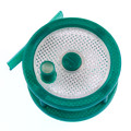
Here it is. See the image attachment. I highlighted the area I am confused about.
- Attachments
-
- The connection points.
Re: A couple of assembly questions.
Yes, simply run wires from the two (+) and two (-) pads to the (+) and (-) connectors on your controller board. You'll have 4 wires going to the phobe to carry the current.
Sublime Layers - my blog on Musings and Experiments in 3D Printing Technology and Art
Start Here:
A Strategy for Successful (and Great) Prints
Strategies for Resolving Print Artifacts
The Eclectic Angler
Re: A couple of assembly questions.
What is the the 3 pads for with the V- V+ on it? I am also guessing I don't solder the thermistor to the board, just run the wire threw the holes right and connect directly to the RAMBo.
Thanks for the help.
Thanks for the help.
Re: A couple of assembly questions.
That pad is how you connect the thermistor to the control board. I recall that you use the (+) and (-) terminals. I'm not sure where the thermistor connects on that heated pad. Maybe someone will pipe in. You could fire an email to SeeMeCnc too.
Sublime Layers - my blog on Musings and Experiments in 3D Printing Technology and Art
Start Here:
A Strategy for Successful (and Great) Prints
Strategies for Resolving Print Artifacts
The Eclectic Angler
Re: A couple of assembly questions.
In your image you uploaded, see where it says sensor? Stick the thermistor down there, solder to the tiny plus and minus. If you look at the board and follow the traces, you'll see where the traces go. They go to the plus and minus pads next to the sensor location. You could also Kapton tape the thermistor out in the middle under the bed somewhere and wire the same, skipping the sensor pad and wiring the thermistor to the plus and minus and the same for the wires to wherever you're sensing/controlling. Really you could tape the thermistor where you want and wire it directly skipping the pads if that works for you. You're really only trying to wire the sensor to the board, the pads are there for your convenience if you want.