RAMBo Quad Extruder Extension Development

RAMBo Quad Extruder Extension Development
Ive started work on it. I will post pictures of the schematics I will create when I am finished. This is all the info I have for now.
Re: RAMBo Quad Extruder Extension Development
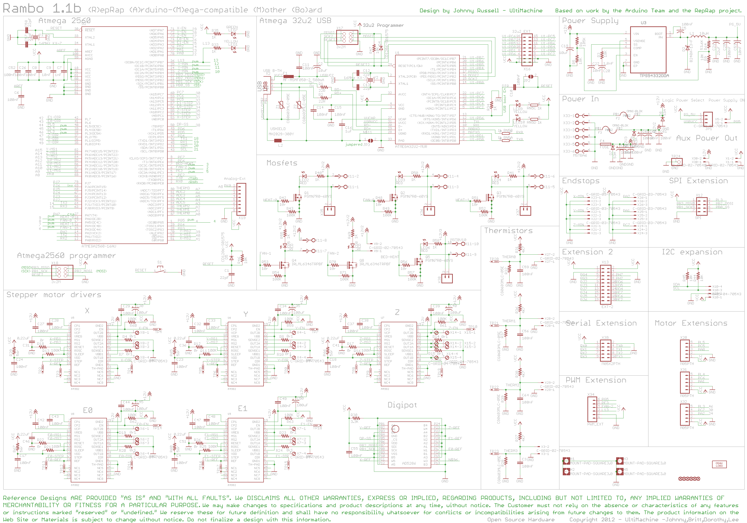
I'm having issues, the schematics on the RepRap wiki do not match the pin assignments defined on the development page. The analog extension output 4 says it's fan 2 on schematics, but on pin assignments it says it is just output 4, not assigned to FAN 2. Also, the pin assignments for all of the motor extensions contradict with the schematic drawing.
http://reprap.org/mediawiki/images/7/75 ... ematic.png" onclick="window.open(this.href);return false;
http://reprap.org/wiki/Rambo_development" onclick="window.open(this.href);return false;
http://reprap.org/mediawiki/images/7/75 ... ematic.png" onclick="window.open(this.href);return false;
http://reprap.org/wiki/Rambo_development" onclick="window.open(this.href);return false;
-
Eaglezsoar

- ULTIMATE 3D JEDI
- Posts: 7185
- Joined: Sun Apr 01, 2012 5:26 pm
Re: RAMBo Quad Extruder Extension Development
You didn't think this would be easy did you?Nylocke wrote:I'm having issues, the schematics on the RepRap wiki do not match the pin assignments defined on the development page. The analog extension output 4 says it's fan 2 on schematics, but on pin assignments it says it is just output 4, not assigned to FAN 2. Also, the pin assignments for all of the motor extensions contradict with the schematic drawing.
http://reprap.org/mediawiki/images/7/75 ... ematic.png" onclick="window.open(this.href);return false;
http://reprap.org/wiki/Rambo_development" onclick="window.open(this.href);return false;
You will get though, I just know you will pursue this until the end.
You don't need it but good luck anyway!
Re: RAMBo Quad Extruder Extension Development
Yeah, I actually did  I may end up checking which pin is which with the RAMBo I have.... Some LEDs I need...

Re: RAMBo Quad Extruder Extension Development
Why do you say the pin assignments for the motor extensions contradict with the schematic? For Motor extension 1 (X20 in the schematics), Pin 5 is connected to PL5, Pin 4 is connected to PC5 and Pin 3 is connected to PA0. Then in the pin assignments I see these:Nylocke wrote:I'm having issues, the schematics on the RepRap wiki do not match the pin assignments defined on the development page. The analog extension output 4 says it's fan 2 on schematics, but on pin assignments it says it is just output 4, not assigned to FAN 2. Also, the pin assignments for all of the motor extensions contradict with the schematic drawing.
http://reprap.org/mediawiki/images/7/75 ... ematic.png" onclick="window.open(this.href);return false;
http://reprap.org/wiki/Rambo_development" onclick="window.open(this.href);return false;
40 PL5 ( OC5C ) Digital pin 44 (PWM) MX1-5 Direction
58 PC5 ( A13 ) Digital pin 32 MX1-4 Step
78 PA0 ( AD0 ) Digital pin 22 MX1-3 Enable
Similarly, Motor extension 2 has 5 to PL4, 4 to PC6 and 3 to PA1 in the schematic. Then these pin assignments in the dev page:
39 PL4 ( OC5B ) Digital pin 45 (PWM) MX2-5 Direction
59 PC6 ( A14 ) Digital pin 31 MX2-4 Step
77 PA1 ( AD1 ) Digital pin 23 Y Max, MX2-3 Enable
Those seem consistent to me -- what am I missing?. Obviously there's a problem with the motor extension pins also being used for the MAX end stops
Re: RAMBo Quad Extruder Extension Development
Gah you're right, I was over analyzing or something, doh. The pin assignments will have to be reassigned to the min stops being the max stops in the firmware, simple fix  this mod will require some heavy modifications to firmware... Also some test subjects
Re: RAMBo Quad Extruder Extension Development
Okay, cool! I thought perhaps I didn't understand the diagramsNylocke wrote:Gah you're right, I was over analyzing or something, doh. The pin assignments will have to be reassigned to the min stops being the max stops in the firmware, simple fix
Also, are you planning on micro-stepping the extra 2 extruders? I guess you'll need to use 4 of the analog extension pins for those and the remaining analog extension pin for the extra thermistor.
Sounds like a fun project
Re: RAMBo Quad Extruder Extension Development
I'm using pololus so they just are using jumpers. I know about the analog extension, 2 more analogs for the thermistor. Since this mod is meant for the MAX, and most printers don't use min and max endstops anymore, I think that the change will be fine.
Re: RAMBo Quad Extruder Extension Development
Does anyone know if the 12v aux out on the RAMBo is fused or not? And if it is, which fuse is it connected to?
-
Eaglezsoar
- ULTIMATE 3D JEDI
- Posts: 7185
- Joined: Sun Apr 01, 2012 5:26 pm
Re: RAMBo Quad Extruder Extension Development
There are two aux power out, the one up by the USB port is Aux Power Out Mosfet and is connected to the Mosfet fuse F3Nylocke wrote:Does anyone know if the 12v aux out on the RAMBo is fused or not? And if it is, which fuse is it connected to?
The other is Aux Power Out Motor and is connected to Motor Fuse F2
Re: RAMBo Quad Extruder Extension Development
How do you know that? Is it possible to figure that out from the schematics or other wiki pages? Or have you used a multimeter to determine what's going where on an actual board?Eaglezsoar wrote:There are two aux power out, the one up by the USB port is Aux Power Out Mosfet and is connected to the Mosfet fuse F3Nylocke wrote:Does anyone know if the 12v aux out on the RAMBo is fused or not? And if it is, which fuse is it connected to?
The other is Aux Power Out Motor and is connected to Motor Fuse F2
Re: RAMBo Quad Extruder Extension Development
Ok, I'll just add another fused 12v input for the extension, no biggie.
Re: RAMBo Quad Extruder Extension Development
alright here is what i got for running the extruder motors using just 1 motor driver on the rambo.
using shift registers the amount of extruders is endless. but would require 2 digital outputs from RAMBo to set them up. This image is just a single 8 bit shift and it runs 2 steppers.
input into register 11110000 and you would enable one stepper, or input 000011111 and it would enable control over the other stepper.
my thought process would be to save as many pins as possible... i cant foresee a reason to ever run multiple extruders at the same time so this should work.
separate heaters and thermisters would still need to be configured.
[img]https://lh6.googleusercontent.com/-H-Gq ... Slide1.PNG[/img]
Re: RAMBo Quad Extruder Extension Development
One reason to run multiple extruders at the same time would be for "mixing" whatever they're extruding (e.g. imagine they're extruding colored inkbubbasnow wrote: i cant foresee a reason to ever run multiple extruders at the same time so this should work.
]
Re: RAMBo Quad Extruder Extension Development
that would be sick, but it could probably be better achived by something like the http://www.filastruder.com/ not at the hot enddpmacri wrote:One reason to run multiple extruders at the same time would be for "mixing" whatever they're extruding (e.g. imagine they're extruding colored inkbubbasnow wrote: i cant foresee a reason to ever run multiple extruders at the same time so this should work.
]).
-
Eaglezsoar
- ULTIMATE 3D JEDI
- Posts: 7185
- Joined: Sun Apr 01, 2012 5:26 pm
Re: RAMBo Quad Extruder Extension Development
By measuring an actual board. There is one change however, the newer boards have a 5 volt output where the Aux Power Out Mosfet used to be and the 5 volts does not appear to be fuse protected.dpmacri wrote:How do you know that? Is it possible to figure that out from the schematics or other wiki pages? Or have you used a multimeter to determine what's going where on an actual board?Eaglezsoar wrote:There are two aux power out, the one up by the USB port is Aux Power Out Mosfet and is connected to the Mosfet fuse F3Nylocke wrote:Does anyone know if the 12v aux out on the RAMBo is fused or not? And if it is, which fuse is it connected to?
The other is Aux Power Out Motor and is connected to Motor Fuse F2
The Aux Power Out Motor which is the one I think Nylocke is talking about is definitely connected to fuse F3. I wish they would update the Wiki when they update the boards.
What used to be called Aux Power Out Motor is now called 5V Aux. I pulled both F2 and F3 and the 5 volts remained on the 5V Aux. The images and schematic need updated on the Wiki.
Re: RAMBo Quad Extruder Extension Development
I just have it set up to use 3 pins per controller. If you wanna experiment with the shift registering stuff then you can yourself, the purpose of this mod is to add 2 extra extruders and make it simple enough for a intermediate hacker to put it together. I'm just going to fuse a new 12v input, 5 amps sound good?
Re: RAMBo Quad Extruder Extension Development
I think it's a long ways off, but ideally you'd want to mix the desired color right at extrusion time so you can produce a wide range of colors without needing MANY extruders and MANY filament rolls (i.e. just CMYKW mixed in varying degrees). Alternatively, what I've been thinking about is whether or not you could do a second pass over a layer of nylon and dye it with CMYK mixtures of RIT dyes.bubbasnow wrote:that would be sick, but it could probably be better achived by something like the http://www.filastruder.com/ not at the hot enddpmacri wrote:One reason to run multiple extruders at the same time would be for "mixing" whatever they're extruding (e.g. imagine they're extruding colored inkbubbasnow wrote: i cant foresee a reason to ever run multiple extruders at the same time so this should work.
]
-
Eaglezsoar
- ULTIMATE 3D JEDI
- Posts: 7185
- Joined: Sun Apr 01, 2012 5:26 pm
Re: RAMBo Quad Extruder Extension Development
dpmacri wrote:
I think it's a long ways off, but ideally you'd want to mix the desired color right at extrusion time so you can produce a wide range of colors without needing MANY extruders and MANY filament rolls (i.e. just CMYKW mixed in varying degrees). Alternatively, what I've been thinking about is whether or not you could do a second pass over a layer of nylon and dye it with CMYK mixtures of RIT dyes.[/quote]
These are all great ideas! The future of 3D printing looks bright indeed if all of these ideas can be followed through with and be available to us hackers.
Your idea of mixing colors on the fly is an especially fine idea that would require a lot of problems to be solved but the benefits would be great. Never stop thinking of these ideas that's how the future is created.
Re: RAMBo Quad Extruder Extension Development
I have a roughly sketched version of the schematic in my notebook, Ill attach it. Its mainly based on RAMPS electronics, mainly because RAMPS seemed the most accessible to hackers, and a bit easier to understand for me (mainly because of the blurry low quality schematic on the RepRap wiki of RAMBo)
I don't really have the money or resources to test this out, nor do I have a MAX or RAMBo based printer to use it with, but if someone could actually make one to verify things work, modify the firmware to make it work, that would be awesome to see, or if anyone has any critiques on it, I can modify it, or best yet, if someone could make a more official looking schematic or even a trace pattern for people to make their own boards for this (rather than hacking together something on a breadboard) that would be AWESOME. Hopefully this will be of help to you guys. All of the ports on the side are the outputs from the RAMBo that you will need to use (except the 12V power, which would need to be a terminal on the board) and connect to the board. The number assigned to them are the pin numbers in Arduino, anything with a P## is a digital pin, and anything with an AP## is an analog pin.

Re: RAMBo Quad Extruder Extension Development
The filament color mixing has been done by RichRap for over a year as a fun splash of things http://richrap.blogspot.com/2012/08/3-w ... olour.html, but the ability to plan out colors is significantly hampered by computing and physical problems. Computing the quantities necessary of each filament would significantly slow down a slice. AMF file format offers the opportunity to specify colors much more easily than STL but even that would require more of an approach of loading solid colors and printing solid colors, not mixing them. Plus, and particularly on a delta bot, the limits of an arduino chip are being met frequently with movement planning. The planning necessary to have the correct colors of filament mixing would extend WELL beyond arduino. Physically, the precision necessary to mix those colors on the fly is dramatically hindered by the hysteresis between extruder and hotend on a bowden setup. Once one of those problems gets solved, I would imagine the other would follow shortly...
Re: RAMBo Quad Extruder Extension Development
Thanks, Eaglezsoar! I'm not the first to think of all of these ideas. See here: http://richrap.com/?p=121. However, I think the dyeing extruder is originalEaglezsoar wrote:dpmacri wrote:
I think it's a long ways off, but ideally you'd want to mix the desired color right at extrusion time so you can produce a wide range of colors without needing MANY extruders and MANY filament rolls (i.e. just CMYKW mixed in varying degrees). Alternatively, what I've been thinking about is whether or not you could do a second pass over a layer of nylon and dye it with CMYK mixtures of RIT dyes.
These are all great ideas! The future of 3D printing looks bright indeed if all of these ideas can be followed through with and be available to us hackers.
Your idea of mixing colors on the fly is an especially fine idea that would require a lot of problems to be solved but the benefits would be great. Never stop thinking of these ideas that's how the future is created.
- Insulin cartridge
Then, the cartridge is connected with a Luer lock to a tubing with a plug at the end. It looks like this:
- Insulin cartridge with tubing
My current concerns are (there will be more
1) That adding the dye would cool things too much and cause poor layer adhesion for subsequent layers.
2) The surface tension of the dye might make it difficult to get good accuracy.
3) That I don't have the necessary skils to actually get it to work
Anyway, that's why I've been following this Quad extruder thread so closely
Re: RAMBo Quad Extruder Extension Development
This was meant to compliment the coming of the Kraken from E3D, but thats a rather interesting use too. Cool guys
-
pyrophreek
- Printmaster!
- Posts: 62
- Joined: Tue Oct 01, 2013 8:56 pm
- Location: Vancouver, CA
Re: RAMBo Quad Extruder Extension Development
Just an idea, but if I recall correctly, there is a I2C communication port on the Rambo. Would it be possible to use that to interface with a small breakout board which controls the additional extruder/Hotend?
Re: RAMBo Quad Extruder Extension Development
Hi All, Im really a newbie in this but what I understand is that you can put drivers, mosfet, etc and conect everything to a I2C port and control all with 2 or 3 cables and be able to program like a normal port or probably im wrong, but lets make the kraken to be alive, any one can recomend a cartesian configuration to mount this ? Im thinking in invest a bit more and get some nice linear guides anybody can recomend something
Regards
Regards