My DELTA-1
-
BenTheRighteous
- Printmaster!
- Posts: 695
- Joined: Fri Nov 07, 2014 9:38 am
Re: My DELTA-1
Wow! The fact that it works at all is incredible. I could never get this far entirely on my own. You should be proud of yourself!
nitewatchman wrote:it was much cleaner and easier than killing a chicken on top of the printer.
-
Khalid Khattak
- Printmaster!
- Posts: 276
- Joined: Thu Dec 11, 2014 12:50 am
Re: My DELTA-1
Ben..reading the posts in this forum helped me a lot....The community is great and i wish to get print like yours with my this printer...
-
Eaglezsoar

- ULTIMATE 3D JEDI
- Posts: 7185
- Joined: Sun Apr 01, 2012 5:26 pm
Re: My DELTA-1
Do you have the link to dart games, google brings up a lot of hits.Khalid Khattak wrote:@teoman..didn't think of that... and i got the magnets from Dart games... These are assembled in metallic casing and the good thing is that the back side of casing has M5 tapping...

-
Khalid Khattak
- Printmaster!
- Posts: 276
- Joined: Thu Dec 11, 2014 12:50 am
Re: My DELTA-1
Hi,
I got the dart game from local seller in Pakistan. These games are easily available in kids toy shop. However, i got the complete game which comes with 6Ea magnetic darts and it cost me 6.5US dollar for complete Dart game. I spent 12US dollar to purchase two dart games ( to get 12 magnets).. scrapped the boards... You check your local shops. Else you can search Aliexpress: for example with a quick search i find:
http://www.aliexpress.com/item/Free-Shi ... 70392.html" onclick="window.open(this.href);return false;
The above comes with only magnetic dart Qty: 03 Ea US 5$ free shipping. In bulk you can further reduce the price.
and here is 100pieces at a cost of $40US+Free shipping.
http://www.aliexpress.com/item/50-pcs-o ... 48107.html" onclick="window.open(this.href);return false;
Last edited by Khalid Khattak on Tue Dec 30, 2014 11:04 pm, edited 1 time in total.
-
Khalid Khattak
- Printmaster!
- Posts: 276
- Joined: Thu Dec 11, 2014 12:50 am
Re: My DELTA-1
Thanks Bone...The more i come closer to completion the more challenging it got... lot of work... 
-
Eaglezsoar
- ULTIMATE 3D JEDI
- Posts: 7185
- Joined: Sun Apr 01, 2012 5:26 pm
Re: My DELTA-1
Yes, thanks for the info! 
-
Khalid Khattak
- Printmaster!
- Posts: 276
- Joined: Thu Dec 11, 2014 12:50 am
Re: My DELTA-1
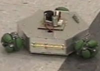
I need help from forum... I want to implement autocalbration function. Can someone see the attached picture and tell What will be Z PROBE OFFSET?especially X&Y values in the following expression:
#define Z_PROBE_OFFSET {X, Y, -Z, 0}
#define Z_PROBE_OFFSET {X, Y, -Z, 0}
- Attachments
-
-
lightninjay

- Printmaster!
- Posts: 289
- Joined: Sun Jul 13, 2014 12:49 am
- Location: Tampa, Florida
Re: My DELTA-1
I don't personally use a Z-probe myself, but I believe that the Z-probe offset will be determined by yourself in where you decide to rig up your z-probe. You will need to directly measure the offset (x and y) of the Z-probe you install, from the X,Y of the center of your printer and/or your nozzle's (0,0) position.
Edit: in looking at your diagram, your offset value would be (0,-28.74) assuming that your X and Y towers sit similarly to the SeeMeCNC towers as the "front" towers of the machine with the Z tower being at 0 degrees or 12' O clock position.
2nd Edit: any forum members with more knowledge than myself about this subject, feel free to chime in, as this is all pure conjecture on my part since I don't use a Z-probe.
If at first you don't succeed, you're doing something wrong. Try again, and if it fails again, try once more. Through trial and error, one can be the first to accomplish something great.
-
Khalid Khattak
- Printmaster!
- Posts: 276
- Joined: Thu Dec 11, 2014 12:50 am
Crash Happens ;)
Hi lightninjay,
Thank you for explaining it in detail. I am confused that the probe X/Y coordinate value should be in Polar format!!!!...i will check putting 0,-28.74 and see what happen. However after running some trial i find that my printer need a very minute calibration..it is cup shape and i get +1mm at edges..centre=0.... I love it... Just want to share one of the crash
https://www.youtube.com/watch?v=pGxnepb ... e=youtu.be" onclick="window.open(this.href);return false;
-
BenTheRighteous
- Printmaster!
- Posts: 695
- Joined: Fri Nov 07, 2014 9:38 am
Re: My DELTA-1
Hah! I've had my layer fan get stuck on my binder clips in a very similar way. I feel your pain!
nitewatchman wrote:it was much cleaner and easier than killing a chicken on top of the printer.
-
Khalid Khattak
- Printmaster!
- Posts: 276
- Joined: Thu Dec 11, 2014 12:50 am
Re: My DELTA-1
one more video of testing this beast at its limit ..i was checking whether the magnetic joints disengage at high acceleration/deceleration AKA jerks..but it passed the test ...
https://www.youtube.com/watch?v=4IVs38I ... e=youtu.be" onclick="window.open(this.href);return false;
https://www.youtube.com/watch?v=4IVs38I ... e=youtu.be" onclick="window.open(this.href);return false;
Re: My DELTA-1
[quote="lightninjay", your offset value would be (0,-28.74) [/quote]
I agree that your probe is offset 0 in X, -28.74 in Y, and in Z that is something that you need to determine. You have to calibrate your Calibration probe before you can calibrate with it .
.
The 'problem' with a contact type Z probe is that while you are using it, it needs to have a Z position lower than your nozzle, and then when you print it has to be raised out of the way so it does not hit your print. If your probe is a inductive pickup, it could have a Z position a few mm above your nozzle so that it is always out of the way of the print and does not need to be moved. However, that assumes that it can read distances of a few mm (which I think they can).
A problem I thought of is that the inductive pickup has to read through the glass and then if you are using a standard Bed which is a PCB with copper heating element traces I don't think the inductive pickup would work very consistantly. If you had a big aluminum or steel plate under your glass, then I think an inductive pickup could be made to work very well.
I agree that your probe is offset 0 in X, -28.74 in Y, and in Z that is something that you need to determine. You have to calibrate your Calibration probe before you can calibrate with it
The 'problem' with a contact type Z probe is that while you are using it, it needs to have a Z position lower than your nozzle, and then when you print it has to be raised out of the way so it does not hit your print. If your probe is a inductive pickup, it could have a Z position a few mm above your nozzle so that it is always out of the way of the print and does not need to be moved. However, that assumes that it can read distances of a few mm (which I think they can).
A problem I thought of is that the inductive pickup has to read through the glass and then if you are using a standard Bed which is a PCB with copper heating element traces I don't think the inductive pickup would work very consistantly. If you had a big aluminum or steel plate under your glass, then I think an inductive pickup could be made to work very well.
-
Khalid Khattak
- Printmaster!
- Posts: 276
- Joined: Thu Dec 11, 2014 12:50 am
Re: My DELTA-1
Hi Tonkabot,
Thanks for reply. I am still confused with WHY the Probe offset for X=0?...
I am using inductive probe and it maximum sensing distance (gap)=4mm. I am using 3mm glass. I shall use Aluminum foil adhesive tape as shown in attached picture at glass back side ( non printing side). This way i hope i will get the inductive probe working. Else i am seeing for CS plate only to be used for one time calibration and then i shall use 3mm glass.
The inductive probe very easily detect the Aluminum foil tape.
As far as Z-height setting and probe calibration is concerned i shall just touch the hotend nozzle tip with glass plate and then measure the gap between the probe tip with glass using FEELER GAUGE.
I have to modify Marlin auto-calibration routine to work with inductive probe.
- Attachments
-
Re: My DELTA-1
Khalid Khattak wrote:Hi Tonkabot,
Thanks for reply. I am still confused with WHY the Probe offset for X=0?...
I am using inductive probe and it maximum sensing distance (gap)=4mm. I am using 3mm glass. I shall use Aluminum foil adhesive tape as shown in attached picture at glass back side ( non printing side). This way i hope i will get the inductive probe working. Else i am seeing for CS plate only to be used for one time calibration and then i shall use 3mm glass.
The inductive probe very easily detect the Aluminum foil tape.
As far as Z-height setting and probe calibration is concerned i shall just touch the hotend nozzle tip with glass plate and then measure the gap between the probe tip with glass using FEELER GAUGE.
I have to modify Marlin auto-calibration routine to work with inductive probe.
The coordinates for the delta printer are already translated from the delta arrangement, so the X,Y,Z are all cartesian. So X is left and right, Y 90 degrees to it forward and back.
And of course Z is up and down. The towers are unfortunately named X,Y, and Z but they have nothing to do with the cartesian coordinate system.
so the offset is in the cartesian coordinate system. and your probe, going by your image of the end effector, is at the same X=0 as the print head. The center of your print bed is at X=0, Y=0, and Z= 393.96mm (in my case for my rostock max V2 - yours is different). The home position at the top of the tower is at (0,0,0).
And as long as the pickup only detects the aluminum tape, it sounds like it should work fine. Although any bubbles or bumps in it will probably be detected. just a sheet of aluminum foil from the kitchen without any adhesive might be flatter, although it might not stay put. you can always pop the bubbles with a pin, but then even the pinhole might be detected.
Last edited by Tonkabot on Thu Jan 01, 2015 10:39 am, edited 1 time in total.
-
lightninjay
- Printmaster!
- Posts: 289
- Joined: Sun Jul 13, 2014 12:49 am
- Location: Tampa, Florida
Re: My DELTA-1
Hopefully this helps clear up some of the confusion! The Delta build plate is split into the four positive and negative quadrants of an intersecting X and Y axis.
Here's a diagram to hopefully clarify
Here's a diagram to hopefully clarify
If at first you don't succeed, you're doing something wrong. Try again, and if it fails again, try once more. Through trial and error, one can be the first to accomplish something great.
-
Khalid Khattak
- Printmaster!
- Posts: 276
- Joined: Thu Dec 11, 2014 12:50 am
Re: My DELTA-1
Tonkabot..very very well explained...
lightninjay... Your diagram in connection with Tonkabot helped me a lot.
I am very thankful of both of you for such a great help.
Today i shall see the probe to work with Aluminum foil. Otherwise i shall use bare PCB board below the glass plate as in somewhere else i read that copper is more sensitive to inductive sensors and can detect at longer distance.
Regards
-
Khalid Khattak
- Printmaster!
- Posts: 276
- Joined: Thu Dec 11, 2014 12:50 am
Re: My DELTA-1
I am planning to print PLA stuff..is it necessary to install heat bed? or does PLA require the platform bed to be heated?
Re: My DELTA-1
My concern with just using the copper of the build plate for your inductive pickup to sense is that the copper is laid out in spirals, and there are gaps between the spirals.Khalid Khattak wrote:Tonkabot..very very well explained...
lightninjay... Your diagram in connection with Tonkabot helped me a lot.
I am very thankful of both of you for such a great help.
Today i shall see the probe to work with Aluminum foil. Otherwise i shall use bare PCB board below the glass plate as in somewhere else i read that copper is more sensitive to inductive sensors and can detect at longer distance.
Regards
So unless the top of the build plate has a solid copper plane (which I don't think it does but I am not sure, also a new plate could be made with one if inductive sensing becomes popular) the inductive pickup will need to be positioned above the copper traces and not bare fiberglass (bare PCB).
What is the diameter of your inductive pickup? I suppose I should look at the gerber files of the build plate to answer some of these questions (the gerbers tell where the copper is and is not on a PCB)
Also, I am guessing that if the inductive pickup is only sensing the copper heating traces in the bed, that when the heater switches on and off that electrical noise from that will be detected. With software the heater could be turned off during the times the inductive pickup is read.
-
Khalid Khattak
- Printmaster!
- Posts: 276
- Joined: Thu Dec 11, 2014 12:50 am
Re: My DELTA-1
its 12mm diameter probe... For bare PCB i mean the plain PCB not the heating bed PCB with tracing ( I have 300mm x 300mm PCB board which i etch to make circuits).... I think for PLA i not need the heating bed PCB... Let me think what good solution i comeup with
Re: My DELTA-1
As long as your bare PCB is flat to the glass, I think the inductive pickup should work good.Khalid Khattak wrote:its 12mm diameter probe... For bare PCB i mean the plain PCB not the heating bed PCB with tracing ( I have 300mm x 300mm PCB board which i etch to make circuits).... I think for PLA i not need the heating bed PCB... Let me think what good solution i comeup with
As to PLA and unheated bed, I don't know. My bed runs at 60c when printing PLA, and it sticks really well with just some hairspray.
I have not tried printing with a cold bed.
-
Khalid Khattak
- Printmaster!
- Posts: 276
- Joined: Thu Dec 11, 2014 12:50 am
Re: My DELTA-1
Thanks for the information .... but have seen some of 3d delta i.e. mini Kossel etc are printing PLA on bare glass ... I have to keep the option of heating bed in the new arrangement
-
Khalid Khattak
- Printmaster!
- Posts: 276
- Joined: Thu Dec 11, 2014 12:50 am
Re: My DELTA-1
I needed a bigger bed to print large 3D models....so back to the drawing board (computer), spent an hour designing the bed that can capable of accommodating PCB heater and metallic plate 340mm diameter that i salvaged from DART GAME ... Fired my CNC machine, The bed was two sided machined out of 16mm MDF and took one hour to complete... I used 16mm and 6.5mm end mill cutters and 3mm drill bit .... The last picture shows how accurately the plate set on the MDF bed
I needed the 1mm CS galvanized plate on the bed because the inductive proximity probe shall be used to auto-level/auto calibrate the bed...
Will share some more picture of final assembly on the machine.
I needed the 1mm CS galvanized plate on the bed because the inductive proximity probe shall be used to auto-level/auto calibrate the bed...
Will share some more picture of final assembly on the machine.
- Attachments
-
-
-
-
Khalid Khattak
- Printmaster!
- Posts: 276
- Joined: Thu Dec 11, 2014 12:50 am
Re: My DELTA-1
If the guys from DART GAME maker knows the complete kit being used in 3D printer they will hike the price of it
-
Khalid Khattak
- Printmaster!
- Posts: 276
- Joined: Thu Dec 11, 2014 12:50 am