I wanted to give my Rostock V2 a nice upgrade and installed the new Cheapskate Carriage Set, the SeeMeCNC EZR Struder,
the HE280 Hotend, the Rostock MAX Ball-Cup Delta Arm Kit and the Hotend Whip.
I assembled everthing thoroughly according to the plan. But after I switched the printer on and installed the new firmware the printer does not react to any commands!!! The screen on the printer just shows firmwaredate and modelltype. The knob has no more function and if I try to home the towers through Mattercontrol nothing happens!!! The only thing running are the fans.
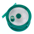
I don't know if that gives a hint but on the left upper corner of the ramboboard is an orange led blinking 2 times and then pausing.
right above a green one that is constanly shining.
Any suggestions what I can do??? I am so desperate...
Thank you
- the screen stays this way
->Communication State: AttemptingToConnect
->M105
->M105
<-start
->Communication State: Connected
<-
->M115
<-Transformation matrix: 1.000000 0.000000 0.000000 0.000000 1.000000 0.000000 0.000000 0.000000 1.000000
<-
<-Free RAM:879
<-
<-Autoretract:0
<-
<-X:0.00 Y:0.00 Z:0.000 E:0.0000
<-
<-SpeedMultiply:100
<-
<-iis2dh accelerometer initializing...
<-
<-start
<-
->M114
<-Transformation matrix: 1.000000 0.000000 0.000000 0.000000 1.000000 0.000000 0.000000 0.000000 1.000000
<-
<-Free RAM:879
<-
<-Autoretract:0
<-
<-X:0.00 Y:0.00 Z:0.000 E:0.0000
<-
<-SpeedMultiply:100
<-
<-iis2dh accelerometer initializing...
<-
<-start
<-
->M105
<-Transformation matrix: 1.000000 0.000000 0.000000 0.000000 1.000000 0.000000 0.000000 0.000000 1.000000
<-
<-Free RAM:879
<-
<-Autoretract:0
<-
<-X:0.00 Y:0.00 Z:0.000 E:0.0000
<-
<-SpeedMultiply:100
<-
<-iis2dh accelerometer initializing...
<-
<-start
<-
->G28 X0
...
...
...