BETA testers discussion
Re: BETA testers discussion
Wow, that's a sprint build! My plate was a bit tight too. I used a file on the tabs to help the fit. Note the recent post on my thread about the lower T-slot mounts. I had mine up too high - they should go BETWEEN the plate and lower plate. I still need to change mine but fighting firmware at the moment!
Sublime Layers - my blog on Musings and Experiments in 3D Printing Technology and Art
Start Here:
A Strategy for Successful (and Great) Prints
Strategies for Resolving Print Artifacts
The Eclectic Angler
-
Kevinvandeusen
- Printmaster!
- Posts: 123
- Joined: Wed Mar 05, 2014 9:53 pm
- Location: Cooley Springs,SC
Re: BETA testers discussion
I also had the projector plate tight, a little sanding fixed it. Also the extrusion scrapes just slightly on the nuts at the top, maybe move to nut over a hair on the next set of melamine. I have the melamine done, now to work on the electronics. Anyone know if we are getting petri dishes, or do we source our own?
Distributor of SeeMeCNC in South Carolina
Re: BETA testers discussion
Ok, so sat down and started putting this thing together. Hit the follow snags:
1. Mis-placement of tab of left side of projector mounting melamine.
2. Hole in mirror mount is not of sufficient diameter for the plastic 10-32 thumb screw.
- EDIT: Apparently the plastic screw is just supposed to thread into the wood. Brilliant idea..... /s
3. Mis-placement of tabs on lower melamine bit that extrusion sits in.
4. Hole in same melamine as mentioned in #3 for extrusion slightly too small.
5. There is no corresponding nut for the mirror holder plastic screw.
- EDIT: Same note as 2.
Also I seem to be missing a few parts:
1. 1xDelrin Bearing Sleave
2. Left door side melamine.
3. Right door side melamine.
Some general comments:
[moderator edit - seriously, no need to use foul language and adding a "*" doesn't cut it.]
[Non-moderator edit - Seriously mom. Calm down. We're all adults here.]
- Metric and SAE? Pick one, use it.
- Phillips and slotted? Pick one, use it.
- Plastic screws into metal threads? This will last all of a week.
- Plastic screws in general. What is this, North Korea?
- Nut traps could use a looser tolerance. Several required shaving to get a nut in.
That is all for now. Will weight in again tomorrow.
Last edited by Chewy64 on Wed Aug 27, 2014 11:45 am, edited 2 times in total.
Re: BETA testers discussion
you should have a metal 10-32 bolt in there... thats used to thread the wood for the plastic thumb screw... it doesnt bolt on, threading the wood allows you to loosen and adjust mirror height from the front of the machine
Guanu
Guanu
Re: BETA testers discussion
I didn't have a 10-32 bolt for this purpose but I certainly have 10-32 taps that I can use. Thanks!
Sublime Layers - my blog on Musings and Experiments in 3D Printing Technology and Art
Start Here:
A Strategy for Successful (and Great) Prints
Strategies for Resolving Print Artifacts
The Eclectic Angler
Re: BETA testers discussion
Chewy64 and I had a hangout last night and built 90% of our droplits. We began at 9PM and concluded at 12:15AM. Therefore, some of our notes are going to be the same.
Notes:
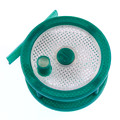
-mirror holder needs a nut and screw to hold it in place. It will fall out during travel/transport otherwise
-the projector base tabs do not fit properly. I had to file both of them down.
-the piece with the petrie dish cutout needed to be filed down as well.
-the top endstop assembly needs to be assembled and then fitted with tslot *before* it gets mounted on the droplit. When mounting it, a thin, long phillips screwdriver should be used since clearance between the screw and the tslot is very tight.
-the stage holders should be using metal screws, not plastic. This is going to be an assembly I am going to be using constantly when changing the petrie dishes. I don't want it to break on me.
-as mhackney stated in his build thread, the holes for the arduino were not correct. New holes had to be drilled in the projector base.
Missing:
-all acrylic
-4x small screws and nuts (used for the endstop and door)
Notes:
-mirror holder needs a nut and screw to hold it in place. It will fall out during travel/transport otherwise
-the projector base tabs do not fit properly. I had to file both of them down.
-the piece with the petrie dish cutout needed to be filed down as well.
-the top endstop assembly needs to be assembled and then fitted with tslot *before* it gets mounted on the droplit. When mounting it, a thin, long phillips screwdriver should be used since clearance between the screw and the tslot is very tight.
-the stage holders should be using metal screws, not plastic. This is going to be an assembly I am going to be using constantly when changing the petrie dishes. I don't want it to break on me.
-as mhackney stated in his build thread, the holes for the arduino were not correct. New holes had to be drilled in the projector base.
Missing:
-all acrylic
-4x small screws and nuts (used for the endstop and door)
Re: BETA testers discussion
Well. you blazed the trail and I just had to clear a few weeds along the way...mhackney wrote:Wow, that's a sprint build! My plate was a bit tight too. I used a file on the tabs to help the fit. Note the recent post on my thread about the lower T-slot mounts. I had mine up too high - they should go BETWEEN the plate and lower plate. I still need to change mine but fighting firmware at the moment!
Re: BETA testers discussion
I'm still fighting the homing issue and have an ever-increasing thread on another forum with the developer. I don't want to lead anyone down the wrong path here so when you get to the point if flashing the firmware, give it a go on your own. I'm happy to answer questions but I'd really like to see if anyone else has the problem I am having (and there is another fellow on a Shapeoko that is having what looks to be similar). But homing is such a basic feature that its hard to believe its a firmware bug at this point.
Sublime Layers - my blog on Musings and Experiments in 3D Printing Technology and Art
Start Here:
A Strategy for Successful (and Great) Prints
Strategies for Resolving Print Artifacts
The Eclectic Angler
Re: BETA testers discussion
Because of the way the laser cuts, sometimes on thicker pieces you get a slight widening of a path towards the back side... so it matters which way you put the nut in. One side tight, the other loose. I used that a number of times to pick which side to insert the nut. While a few of mine were really, really tight, overall I really would not want much looser holes.Nut traps could use a looser tolerance. Several required shaving to get a nut in.
Re: BETA testers discussion
BTW the wiring from the top of the cabinet is shown here:
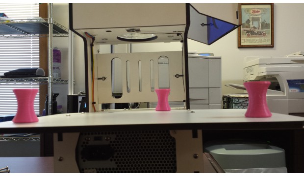
This was posted to show the risers in place, but you can see the wire routing inside the cabinet too.
This was posted to show the risers in place, but you can see the wire routing inside the cabinet too.
Re: BETA testers discussion
did you run all of the stepper wires through that tiny little hole on the platform? I used the larger hole nearer the rear but it is not the best position for the wires.
Sublime Layers - my blog on Musings and Experiments in 3D Printing Technology and Art
Start Here:
A Strategy for Successful (and Great) Prints
Strategies for Resolving Print Artifacts
The Eclectic Angler
Re: BETA testers discussion
Homing? Why are you homing??? You zero the machine out each print by manually turning the drive shaft until the build platform comes in contact with the PDMS in the vat.mhackney wrote:I'm still fighting the homing issue and have an ever-increasing thread on another forum with the developer. I don't want to lead anyone down the wrong path here so when you get to the point if flashing the firmware, give it a go on your own. I'm happy to answer questions but I'd really like to see if anyone else has the problem I am having (and there is another fellow on a Shapeoko that is having what looks to be similar). But homing is such a basic feature that its hard to believe its a firmware bug at this point.
Re: BETA testers discussion
Ok, I have no idea how to run an SLA printer!
Why is there a home switch then? I thought you would set the Z height like on a filament printer.
Why is there a home switch then? I thought you would set the Z height like on a filament printer.
Sublime Layers - my blog on Musings and Experiments in 3D Printing Technology and Art
Start Here:
A Strategy for Successful (and Great) Prints
Strategies for Resolving Print Artifacts
The Eclectic Angler
Re: BETA testers discussion
I used the hold on the platform.mhackney wrote:did you run all of the stepper wires through that tiny little hole on the platform? I used the larger hole nearer the rear but it is not the best position for the wires.
Re: BETA testers discussion
The switch is a limit switch, not a home switch. It's for when the carriage gets to the top.mhackney wrote:Ok, I have no idea how to run an SLA printer!
Why is there a home switch then? I thought you would set the Z height like on a filament printer.
To zero your machine, slowly manually turn the threaded rod until the build platform (hourglass-shape) touches the resin.
Re: BETA testers discussion
Ok, that makes sense. Why have a physical limit switch? Soft limits would work just fine - I do this on my baby CNC mill with no issues whatsoever.
I do see now in the original .8 grbl that is on the github they have configured the switch as a limit switch.
I assume after you touch off on the resin you set Z=0 and then you are ready to go?
I do see now in the original .8 grbl that is on the github they have configured the switch as a limit switch.
I assume after you touch off on the resin you set Z=0 and then you are ready to go?
Sublime Layers - my blog on Musings and Experiments in 3D Printing Technology and Art
Start Here:
A Strategy for Successful (and Great) Prints
Strategies for Resolving Print Artifacts
The Eclectic Angler
Re: BETA testers discussion
You don't zero to the surface of the resin. You zero to the surface of the PDMS. Creation Workshop doesn't require you to set zero via gcode. It just starts running where your build platform is placed.mhackney wrote:I assume after you touch off on the resin you set Z=0 and then you are ready to go?
Put your UV resin in your PDMS-covered vat, manually home the build platform down INTO the resin until it stops against the PDMS. Done. Do NOT crank it back up a turn or two, otherwise you risk losing adhesion if your first layer.
Re: BETA testers discussion
Thanks sgraber. Can you enlighten us about PDMS - where to get it and how to apply it? I have a 100mm borosilicate petri dish arriving today. I was going to use Rainex or something similar.
Once you have the build platform touched off on the bottom of the vat (or the surface on the bottom of the vat) I presume you zero out Z? Is Z+ towards the top of the machine?
Once you have the build platform touched off on the bottom of the vat (or the surface on the bottom of the vat) I presume you zero out Z? Is Z+ towards the top of the machine?
Sublime Layers - my blog on Musings and Experiments in 3D Printing Technology and Art
Start Here:
A Strategy for Successful (and Great) Prints
Strategies for Resolving Print Artifacts
The Eclectic Angler
Re: BETA testers discussion
RainEx won't work. Pretty much PDMS for what you're doing will be the least painful.
http://www.amazon.com/Sylgard-Solar-Enc ... l+silicone
or
http://www.amazon.com/Solar-Encapsulati ... 71Y95J1E3E
Mix 10:1 according to instructions. You don't need more than 10mL mixed per petri. Pour it in, let it de-gas until all the bubbles are gone, and then you can bake it on your printer's HBP @ 90°C for 1-2 hrs.
Z+ is UP. You don't have to set zero at all in gcode or otherwise. Just put the build platform against the PDMS and you're good.
http://www.amazon.com/Sylgard-Solar-Enc ... l+silicone
or
http://www.amazon.com/Solar-Encapsulati ... 71Y95J1E3E
Mix 10:1 according to instructions. You don't need more than 10mL mixed per petri. Pour it in, let it de-gas until all the bubbles are gone, and then you can bake it on your printer's HBP @ 90°C for 1-2 hrs.
Z+ is UP.
Re: BETA testers discussion
Thanks. I also googled PDMS and found your posts on the buildyourownsla forums.
It's at times like these I wish I was still a research chemist! I have a PhD in inorganic chemistry and made silicone containing polymers similar to PDMS!
It's at times like these I wish I was still a research chemist! I have a PhD in inorganic chemistry and made silicone containing polymers similar to PDMS!
Sublime Layers - my blog on Musings and Experiments in 3D Printing Technology and Art
Start Here:
A Strategy for Successful (and Great) Prints
Strategies for Resolving Print Artifacts
The Eclectic Angler
Re: BETA testers discussion
Nope. Or at least, none that are left over. Guess I'll add that to the "missing parts" list. I'm probably going to use a M3 thumb screw and a nut. Any chance we can get the missing parts shipped out? I can't complete the carriage or the door ATM.Guanu wrote:you should have a metal 10-32 bolt in there... thats used to thread the wood for the plastic thumb screw... it doesnt bolt on, threading the wood allows you to loosen and adjust mirror height from the front of the machine
I realize this. Some were too small regardless to get a nut in. I had to file some to get a nut in period.erickphd wrote:Because of the way the laser cuts, sometimes on thicker pieces you get a slight widening of a path towards the back side... so it matters which way you put the nut in. One side tight, the other loose.
Last edited by Chewy64 on Wed Aug 27, 2014 11:25 am, edited 1 time in total.
Re: BETA testers discussion
Also, how does the mirror mount? There is no clamp like mechanism, it seems it is glued or double sided taped?
Sublime Layers - my blog on Musings and Experiments in 3D Printing Technology and Art
Start Here:
A Strategy for Successful (and Great) Prints
Strategies for Resolving Print Artifacts
The Eclectic Angler
-
Kevinvandeusen
- Printmaster!
- Posts: 123
- Joined: Wed Mar 05, 2014 9:53 pm
- Location: Cooley Springs,SC
Re: BETA testers discussion
i am thinking double tape, so it is easy to change if damaged
Distributor of SeeMeCNC in South Carolina
Re: BETA testers discussion
Me too, seems like a logical approach.
Sublime Layers - my blog on Musings and Experiments in 3D Printing Technology and Art
Start Here:
A Strategy for Successful (and Great) Prints
Strategies for Resolving Print Artifacts
The Eclectic Angler
Re: BETA testers discussion
No 10-32 metal bolt in my kit either, but I've got plenty in the hardware stock here.
As for the mirror assembly, I took the plunge and used epoxy glue for the frame with a small amount for the mirror too. I used some small corner squares to insure that the sides were perpendicular during curing, and centered the mirror in the slot. Thankfully the mirror is square so I didn't have to decide orientation...
Also, I am running the stepper wires down the back slot of the extrusion.(NOT!) If you cut off the small tabs either side of the lock tab in the middle of the connector, it slides down through the slot. Of course, you still have to remove the connector to get the wires into the controller, but it sure is easier. You don't need the tabs or lock tab as the socket on the controller doesn't have this feature. If I were going to run the wires down the center hole of the extrusion, I think I'd pass a 22 gauge copper wire (like magnet wire) up the center first, then attach it to the 4 stepper wires and pull it through in one go.
CORRECTION: after getting to the gantry build, it struck me that the rollers use the front and back slot of the extrusion and not the side ones... thus the wires have to go down the center hole... now where is my 22 gauge magnet wire???