
[img]http://www.wetconcepts.com/Bad_1st_Layer_a.jpg[/img]
I've been trying unsuccessfully to get a good first layer print. I'm using a flat, single layer disc from mhackney's Strategy for Successful Prints thread (http://forum.seemecnc.com/download/file.php?id=8475" onclick="window.open(this.href);return false;).
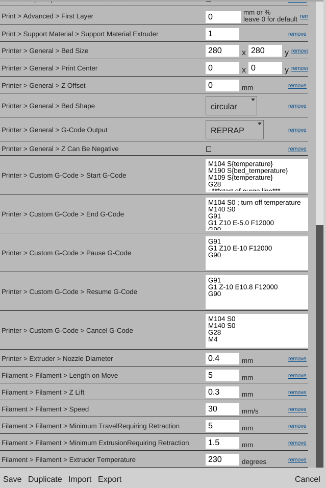
I've used MatterControl/MatterSlice & Cura as well as Simplifiy3D along with switching from the stock hotend (.5 nozzle) to a E3D V6 hotend (.4 nozzle) and the issue happens regardless.
SeeMeCNS Black ABS 1.73 mm
Temp 220 - 235 has been tried
1st layer height is .3 mm, .25, .35. .4 have been tried
1st layer width .4 mm, .35 , .3 , 25 have been tried
Retraction 4
z lift .6
infill overlap .03, .05, .1 have been tried
speed 30, 40, 50
fill rotations 0, 45, 90, 270 all the same results
I've checked the belts, skates, tricklazer arms, calibration is good - all the hardware checks out ok. Extruder nob/hob/gear is clean and looks good.
Any ideas on what to try would be greatly appreciated!
Thanks - Bob
First Layer Frustrations - Resolved
First Layer Frustrations - Resolved
Last edited by BobH on Sat Mar 07, 2015 11:59 am, edited 1 time in total.
Re: First Layer Frustrations
looks simply like an oversquished first layer...
to simply bring it up a hair do this:
click the lcd knob, go to the last menu for advanced settings, click the knob, go down to calibrate z height, click the knob.. click home towers..
after the machine has homed, go down to Z position and click the knob.. turn the knob counter clockwise to bring the hotend down.. turn the knob slowly when it gets close to the glass, then turn it very slowly until the LCD reads 0.10mm and click the knob
go down to set z=0.00 and click the knob..
once you do that, your first layer will be .1mm higher and less squished.. if that is too high and parts will not stick, repeat the process but this time have the LCD read -0.05 (negitive .05) and set z0 at that spot... I prefer to dial my first layer in by how it appears on the bed to get the best results.. this will help you dial in that first layer.
Guanu
Re: First Layer Frustrations
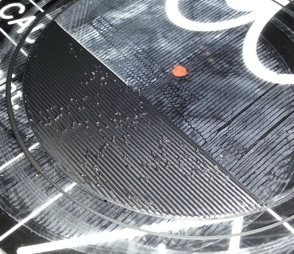
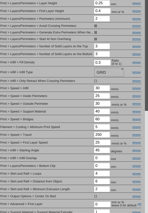
Thanks for the tips Guanu. raising the Z height helped somewhat. I actually raised it up .2 mm - until adhesion was starting to be impacted but, I'm still getting some of the similar roughness. The raised areas appear in the previous line of material after the new infill line travels past it.
[img]http://www.wetconcepts.com/Bad_1st_Layer_b.jpg[/img]
[img]http://www.wetconcepts.com/Slice_Settings_A.png[/img] [img]http://www.wetconcepts.com/Slice_Settings_B.png[/img]
[img]http://www.wetconcepts.com/Bad_1st_Layer_b.jpg[/img]
[img]http://www.wetconcepts.com/Slice_Settings_A.png[/img] [img]http://www.wetconcepts.com/Slice_Settings_B.png[/img]
Re: First Layer Frustrations
Notice that each line is alternately higher or lower on alternating sides depending on which way it was travelling? I have a similar, but less pronounced effect. When a long straight line of infill is drawn in one direction, it starts of high, then ends up low by the end of the line, when it starts a new line right beside where it was just low, it's now high again and the opposite end is now low. It's odd, and I can't quite put my finger on why it's happening. I'm almost thinking it could be accumulated microstepping error or some other resolution limitation. I'm also wondering if it is due to some acceleration settings, because at the moment that it gets lower, is when one tower has to shoot upwards/downwards at a very fast rate... maybe the acceleration of the tower itself is being limited such that it can't achieve it's intended position in time?
*not actually a robot
Re: First Layer Frustrations
Two questions:
Do you have dampers?
Can you provide a much closer image?
I find the current image odd because each 'bead' of plastic looks so very wide in this view. I would not even expect to see the grain in a photo at this distance until we are zoomed in much more.
Do you have dampers?
Can you provide a much closer image?
I find the current image odd because each 'bead' of plastic looks so very wide in this view. I would not even expect to see the grain in a photo at this distance until we are zoomed in much more.
Re: First Layer Frustrations
I do have dampers installed. I've considered removing them, but I was hoping to get a bit better at dialing in this 1st layer before throwing in the towel and removing them.
I don't have a camera that is good at macro pics.
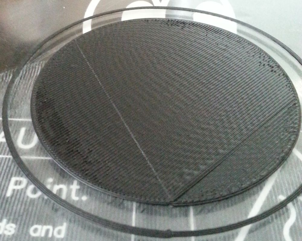
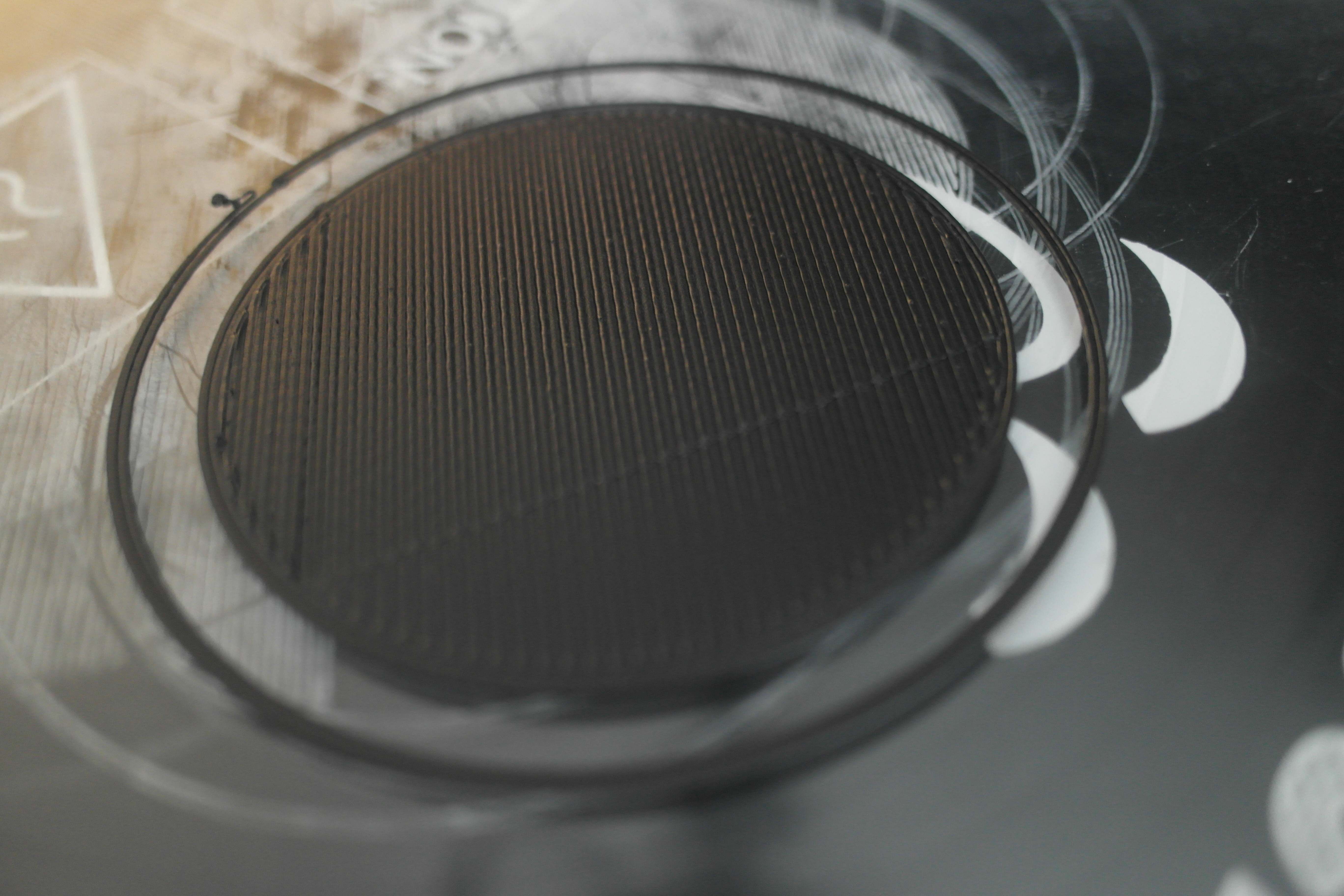
I was able to get some good improvement. I started with raising the z zero value until the roughness disappeared. Then I gradually lowered my z height (per guanu's steps) AND increased the 1st layer width setting. Ended up with a "First Layer Width" setting of .9 for now (matterslice) and the Z zero was very close to what I had with the original "paper" setting during calibratin. When I was having the issue the First Layer Width was set low ~.1 - .5. I'm still playing around to get the 1st layer thickness to come out close to the setting of .35 mm, but it tends to range from .34 to .44 mm. At least most of the roughness with a bead/line has been removed, thankfully.
Thanks for everyone's help so far!
Here's my most recent results;
[img]http://www.wetconcepts.com/Better_1st_layer_b.JPG[/img]
I don't have a camera that is good at macro pics.
I was able to get some good improvement. I started with raising the z zero value until the roughness disappeared. Then I gradually lowered my z height (per guanu's steps) AND increased the 1st layer width setting. Ended up with a "First Layer Width" setting of .9 for now (matterslice) and the Z zero was very close to what I had with the original "paper" setting during calibratin. When I was having the issue the First Layer Width was set low ~.1 - .5. I'm still playing around to get the 1st layer thickness to come out close to the setting of .35 mm, but it tends to range from .34 to .44 mm. At least most of the roughness with a bead/line has been removed, thankfully.
Thanks for everyone's help so far!
Here's my most recent results;
[img]http://www.wetconcepts.com/Better_1st_layer_b.JPG[/img]
-
Eaglezsoar

- ULTIMATE 3D JEDI
- Posts: 7185
- Joined: Sun Apr 01, 2012 5:26 pm
Re: First Layer Frustrations
Looking a lot better! Have you calibrated your cold end extruder?

Re: First Layer Frustrations
I'm trying to picture the layout location. Is that centered on the bed?
Re: First Layer Frustrations
Great progress. Have you polished the tip of your nozzle? This ridges could be scratches or burrs on the nozzle.
Sublime Layers - my blog on Musings and Experiments in 3D Printing Technology and Art
Start Here:
A Strategy for Successful (and Great) Prints
Strategies for Resolving Print Artifacts
The Eclectic Angler
Re: First Layer Frustrations
Calibrated, checked & double checkedEaglezsoar wrote:Looking a lot better! Have you calibrated your cold end extruder?
Re: First Layer Frustrations
You could also try raising your Z-lift a bit, that might stop the dragging across the layers.
Re: First Layer Frustrations
I lost count of the number of discs I've printed, lol. I can never get the 1st layer below a thickness of .4mm even though I lower & lower the z height through the lcd panel. Also, I've started printing a 2nd layer and it now has taken on the characteristics of the 1st bad layer - see my 1st pic. I built a 5' x 9' cnc router & an 18' fishing skiff from scratch. This thing is about to crush my confidence in a big way. I just can't get this thing to print like others I've seen posted in this forum. Maybe it's crappy filament? I don't have any other filament to test at the moment.
I'll give this thing another week, then it will be in the for-sale section that's how frustrated this thing is making me. Sorry for the rant!
I'll give this thing another week, then it will be in the for-sale section that's how frustrated this thing is making me. Sorry for the rant!
Re: First Layer Frustrations
Somebody correct me if I'm wrong here..
My first layer is always lower than my normal layers to get a good squish down on the bed. When you set the overall Z-height from the LCD, you're setting the nozzle height to actually read at Zero. Your software is generating gcode to start that first layer .4mm higher than Zero. Since you have a .4 nozzle on a E3D v6, it's probably not extruding that exact amount, mines roughly .37 when I measure the filament coming out of the nozzle.
I use feeler gauges to set the nozzle height to .08, my first layer is set to .20, every layer after that is .23
Re: First Layer Frustrations
.08 is pretty much the thickness of copier paper, which is where I started this journey. There are just too many variables to pin down on this machine! I'm ripping out the dampers tomorrow.KAS wrote: I use feeler gauges to set the nozzle height to .08, my first layer is set to .20, every layer after that is .23
Re: First Layer Frustrations
One of the best tips I got when I went through a period of not getting ABS to stick well without the Elmers magic was that with a 0.4mm nozzle on the E3Dv6, a layer height of 0.2 is about right. A first layer of more than 0.2 is too much. The zero height is set to the thickness of 80gm copier paper.
Re: First Layer Frustrations
Bob, just for giggles why don't you try the bed level wizard in MatterControl. It won't help a calibration issue, but if the bed has a small physical (or mathematical) tilt to it, it'll be taken care of. I did this with my Orion yesterday to cure a low spot between my x and z towers.
Make sure your bed & hot end are at operating temp before running the wizard.
g.
Make sure your bed & hot end are at operating temp before running the wizard.
g.
Delta Power!
Defeat the Cartesian Agenda!
http://www.f15sim.com - 80-0007, The only one of its kind.
http://geneb.simpits.org - Technical and Simulator Projects
Defeat the Cartesian Agenda!
http://www.f15sim.com - 80-0007, The only one of its kind.
http://geneb.simpits.org - Technical and Simulator Projects
Re: First Layer Frustrations
BobH wrote:.08 is pretty much the thickness of copier paper, which is where I started this journey. There are just too many variables to pin down on this machine! I'm ripping out the dampers tomorrow.KAS wrote: I use feeler gauges to set the nozzle height to .08, my first layer is set to .20, every layer after that is .23
I was looking at your above settings(images) that show the first layer at .40 and the rest .25
Last edited by KAS on Thu Mar 05, 2015 12:23 pm, edited 1 time in total.
Re: First Layer Frustrations
There is a relationship between orifice diameter and layer thickness. Obviously, id the layer height is 2 times the orifice diameter, you will be extruding in air. I typically set layer height to 50% of the orifice diameter. This insures good interlayer adhesion. Of course you can make it smaller to improve the part's Z resolution. As you increase layer height above 50% you can find a sweet spot if you want thicker layers. But anything >80% is not going to provide enough surface area for good first layer adhesion and inter-layer bonding.
Some slicers allow you to set a different first layer thickness than the rest of the part. I don't find I need that. When I print my single layer object at .2mm layer height, I measure it and it will be .2mm. If it is not, I tweak the Z height until it is. Melamine changes dimensions slightly with temperature and humidity so I print one of these EVERY day, measure, tweak and I'm off printing perfect parts. It is critical that your bed and hot end are up to temperature and equilibrated. Give them 10 minutes or so once they are at temp before measuring Z height.
Some slicers allow you to set a different first layer thickness than the rest of the part. I don't find I need that. When I print my single layer object at .2mm layer height, I measure it and it will be .2mm. If it is not, I tweak the Z height until it is. Melamine changes dimensions slightly with temperature and humidity so I print one of these EVERY day, measure, tweak and I'm off printing perfect parts. It is critical that your bed and hot end are up to temperature and equilibrated. Give them 10 minutes or so once they are at temp before measuring Z height.
Sublime Layers - my blog on Musings and Experiments in 3D Printing Technology and Art
Start Here:
A Strategy for Successful (and Great) Prints
Strategies for Resolving Print Artifacts
The Eclectic Angler
Re: First Layer Frustrations
By the way, once I'm in the ballpark with the Z setting, I don't use paper or a feeler gauge to refine it. Do a quick single layer print, measure it with calipers and make an adjustment and be done with it.
Sublime Layers - my blog on Musings and Experiments in 3D Printing Technology and Art
Start Here:
A Strategy for Successful (and Great) Prints
Strategies for Resolving Print Artifacts
The Eclectic Angler
Re: First Layer Frustrations
Yikes, seems like the nozzle is not aligned correct along the z axis on all points!? Or maybe retraction making this happening, care to try changing the retraction.
http://www.3dfilamenta.com: Sell Your 3D Printer Related Products Here
Re: First Layer Frustrations
Despite the fact that the 1st layer was acceptable, the 2nd layer still had similar roughness from the scraping of the nozzle as it passed the previous bead despite trying every setting I thought might help. So last night I removed the dampers, checked skate play & wheel friction, re-tensioned the belts, re-checked tower perpendicularity and this morning I'll recalibrate and see where I am at.
Is there a general troubleshooting guide on the 'net that would apply to delta's and how to tune the bead properties? Seems like my trial & error efforts aren't getting me to where I want to be and no confidence that what I'm changing will have any beneficial impact
Thanks for all the tips everyone. I really appreciate the help. Is there a general troubleshooting guide on the 'net that would apply to delta's and how to tune the bead properties?
Re: First Layer Frustrations
BobH - firstly there really aren't any guides that I know of. Most of us that know this stuff are too selfish to share our knowledge  (you know I'm kidding!) There are just too many variables and it would require a lot of effort to document everything. Here's a good place to start and I will post this as a sticky too.
EDIT: I've posted the sticky here: Strategies for Resolving Print Artifacts
Strategies for Resolving Print Artifacts
When presented with any problem, a time tested approach is to break it down into it's smallest components and determine what you know and down't know about each. This can eliminate a lot of unnecessary effort and help you focus on finding the root issue. In this case, you can break the problem down into a few categories:
1) first layer problems
2) >first layer problems
3) perimeter problems
4) top layer problems
5) fill problems
6) overhang problems
and for each of these there can be:
A) slicing problems
B) mechanical problems
(of course I've simplified this, the model itself (see #6) could be a problem as could electrical issues, etc. But for the majority of the cases, these two will suffice.)
You can attack 1 through 6 in order - and, of course, you might not experience all of these. Here are some strategies:
1) First Layer Problems - follow the recommendations in my Guide and use the single layer object. If slowing down, adjusting extrusion, using the lowest melt temp, etc don't work or i you see artifacts that indicate a mechanical problem, then you need to turn your attention to the mechanical aspects of the machine and work through those until you find and resolve the problem.
2) Greater than First Layer Problems - if you nail the first layer, it goes down nice and smooth without significant artifacts predictably and reliably but are seeing issues in the second or higher layers, this is almost always related to a mechanical problem and not a slicing problem. Think about it, once the first layer is down it has created a "raft" for the next layer and the top surface of that raft should be precisely parallel at any point on the surface to the nozzle tip's motion. In other words, the next bead should go down perfectly. If not, start with the nozzle itself. Polish the tip, check the bore to make sure it is round and has no burrs or significant scratches in it (hold up to light and look through). If you have a spare nozzle, polish it up and try it. Once the nozzle has been eliminated (and nozzle issues would also be prime suspects for #3, #4 and possibly #5) next check the hot end itself. Make sure it is tight with NO WIGGLE whatsoever. One easy test is to re-orient the hot end in the effector (rotate it 90° or 120°) and test print. Does the issue show up in exactly the same place? If so, it is not the hot end, if not, then you have narrowed it down a bit. Don't forget to use the slicer rotate feature to rotate the part, say 90°, and test. The results of this can help determine which tower/s might be contributors.
Think about the delta to cartesian geometry mapping - the Delta Z tower is precisely aligned with the Cartesian Y axis. This is a powerful realization as it allows you to start thinking about the relationship of the tower movements to the part geometry. For instance, if you have print artifacts that are precisely aligned with the Cartesian Y axis no matter how you rotate the part or hot end, that should be screaming "There is a problem along the Z tower mechanical path from the effector up through the arms to the carriage - including the track the carriage rollers ride in". Don't forget the belt, stepper pulley and idler pull at the top. A small piece of debris on the parts can cause the belt to stretch slightly as it goes around the pulley and this can result in a print artifact. A good thing to do is to clean everything carefully (I use windex and clean lint free paper towels) and re-test. It is also a good idea to tighten the pulley grub screws - I can't tell you how many times that has been the issue (especially on the X and Y towers where delta-to-Cartesion coordinate translation is a little less intuitive to figure out).
Next check to see if there is a relationship with the print artifact and either the X or Y towers. If so, try rotating the part in your slicer and rechecking. Move the part closer and further away from a suspect tower and replace and check. This is why I like a simple, small part to test - you might be making a lot of prints and you want to get the data as quickly as possible.
If you discover a relationship, work on the suspect tower as per the Z tower suggestions above. One technique I use is to apply pressure from my finger on the effector aligned with the direction of the suspect tower while it is printing. First towards the tower, then on the other side away from the tower. This eliminates backlash in the system and an help identify issues. You can do both directions on a single print so you get a twofer on this test!
3) Perimeter Problems - these could be caused by either slicing or mechanical problems. Here it is important to think about what could cause the observed artifact. Is it a blob? If so, that is most likely a slicing issue and you should turn your attention to tuning the slicing parameters. Is it a dislocation, i.e. corners or long edges are not completely aligned one on top of each other? If so, that is a mechanical issue and you can use the strategies in #2 above to identify which axis is contributing to the problem.
4) Top Layer Problems - these are somewhat related to #2 in that the top layer is being laid down on what should be a near perfect base. Nozzle imperfections are a prime suspect as is a loose hot end - see the tests and recommendations in #2.
5) Fill Problems - fill problems are more unusual and almost always a slicing issue. Once you have the first layer and perimeters nailed, squirting the plastic inside to fill the part is usually not a problem. Overfilling that caused bulges in higher layers can be an issue. This can be addressed with calibrating the extruder, filament extrusion temperature, infill extrusion width and even infill density.
6) Overhang Problems - firstly, realize there are geometry limitations on what can be printed with a FFF printer! The laws of physics still apply to 3D printing. Overhang issues are almost always related to slicing. There are many different types of overhangs and bridges so I'm not going to attempt them all here. However, a common one is worth discussing. Think about an inverted pyramid - the sides slope up and out creating an overhang. Most slicers default to printing perimeters outside-in. Think about that. What is that outside perimeter going to adhere to? Depending on the slope of the wall, there may be very little plastic underneath from the previous layer. I like to print these inside-out. Think about that. Now, the first inner perimeter will be printed securely on a solid base. The outermost layer will have the advantage of a neighboring layer to stick to, helping prevent it from sagging.
Sublime Layers - my blog on Musings and Experiments in 3D Printing Technology and Art
Start Here:
A Strategy for Successful (and Great) Prints
Strategies for Resolving Print Artifacts
The Eclectic Angler
Re: First Layer Frustrations
mhackney wrote:BobH - firstly there really aren't any guides that I know of. Most of us that know this stuff are too selfish to share our knowledge
EDIT: I've posted the sticky here: Strategies for Resolving Print Artifacts
Strategies for Resolving Print Artifacts
Thanks for all your help & detailed info. Michael! I know it takes a lot of time out of your day to share this information & I can't tell you how much it helps the poor noobs like myself.
Last edited by BobH on Fri Mar 06, 2015 11:22 am, edited 1 time in total.
Re: First Layer Frustrations
Thanks Bob, and I do know how much it helps! I was there once myself.
Cheers,
Michael
Cheers,
Michael
Sublime Layers - my blog on Musings and Experiments in 3D Printing Technology and Art
Start Here:
A Strategy for Successful (and Great) Prints
Strategies for Resolving Print Artifacts
The Eclectic Angler
Re: First Layer Frustrations - Resolved
I found the issue. It was a very stiff Tricklaser ball joint on the skate side of the rod. It appears I accidentally got a tiny amount of thread lock on the ball joint when I put the thread lock on the outside nut that holds the arm on the axle. I replaced the Tricklaser arms with the stock plastics arms, re calibrated, and the printing improved dramatically. It's not perfect yet, but it appears that I am over this 1st hurdle & learning curve. I will admit that I learned a lot while troubleshooting this issue, but the frustration level was high at times. Thanks again to everyone that took the time out of their life to lend a hand to a noobie. It is greatly appreciated & hopefully I can return the favor sometime! - Bob