A few build notes for the RostockMAX v3 Aficionado

The new for 2016 RostockMAX v3!
User avatar
PartDaddy
Printmaster!
Posts: 374
Joined: Fri Mar 23, 2012 4:03 pm

A few build notes for the RostockMAX v3 Aficionado

Post by PartDaddy »

Let's look at some of my mechanical build notes that can effect probing and printing results.

1) Belt Tension: Don't need to sound like a guitar, but not loose. All three tightened the same. Be sure the belts ride over the pulley's nicely. Timing pulley's on the steppers are centered up with the belt and idler's.
v3belttension
v3belttension

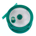
2) Carraige and Platform:
2A) Press-on ball joints firmly and complete first. THEN install washers and screws. If you use the screws the squeeze the ball joints onto the carriage or platform, the ball joints might now seat fully and dimensions and geometry critical to parallel kinematics will be off and cause problems.
2B) During carriage assembly, first check plastic bearing sleeves for strings or burr from machining. Press sleeve firmly onto the R4 bearings. Press each bearing firmly and completely onto the carriages and plastic spring arms. Next be sure the two halves of the carriage fit together with only a small amount of squeeze, then install the three screws to secure the halves. Like the ball joints, using the screws to squeeze and 'seat' the bearings will likely break the plastic.
2C) Install those #4 flat head machine screws square and completely until almost touching the screw holding the ball joint on (and that's the last time you touch the end-stop screws ;) ).
2D) Bowden tube entry and exit from the wire mesh loom can effect bowden-carriage interference, plug connection, and pulling on the platform assembly. Don't exit too close to the top of the hot end - give some wiggle room.
carriage
carriage
platform
platform

3) Bed Clamps: !! Don't over-tighten these !! Gentle clamp pressure. Over-tightened bed clamps can bow or flex the glass build surface. Use a metal straight edge to check flatness of the bed at room temperature. The Onyx rev8 bed is 1mm thick and 'floats' under the glass to compensate minor expansion. The 1mm thickness allows the glass to easily flatten any warping happening to the heater. Also pay attention to tape and LED leads and the three dimples in the plastic bed insulator that help keep the bed heater (Onyx rev8) aligned. The blocks supporting everything have two different heights. I recommend the deeper side and the glass will sit flush and nicer with the surface of the printer.
bed clamping
bed clamping

4) Wiring / Electrical: I just built this v3 in the pictures last week. It works great and it probed and printed first time, like all our other production printers. I did tweak the z probe offset a little more to bring in an even surface (tuned out about .003") Looking at my pictures, the guys thought it was funny I looped all of my end stop wires together and didn't cut them short. I wanted to do something that might cause noise issues - YOU should cut them down shorter. I did keep my stepper wires away from end-stop and control wires. The I2C going down the bowden line next to the hot end and part fan doesn't matter because the BED and HOT END are NOT ON during probing. I know, you might be thinking, 'what about the probe wires beside the hot end or part fan pwm wires?' We'll, probing is done while the hot end is room temperature and fans are turned off. So nothing is happening there to mess with I2C wires. If you are trying to auto-probe and heat is on, then you're doing it wrong or you have the wrong firmware installed on your printer.
wiring1
wiring1
wiring2
wiring2


Lastly, I made a 275mm diameter calibration print. Find it here: http://repables.com/r/800/
v3 275mm dia calibration print

*** Please check our github for firmware updates *** Our next update will likely be 2016-NOV-11 Friday.
~PartDaddy
SeeMeCNC Owner & Founder
Blackpoint Engineering is SeeMeCNC
Since 1996
User avatar
mhackney
ULTIMATE 3D JEDI
Posts: 5412
Joined: Mon Mar 26, 2012 4:15 pm
Location: MA, USA
Contact:

Re: A few build notes for the RostockMAX v3 Aficionado

Post by mhackney »

Steve, the bed mount is the only difference I see on how I assembled my V3. This is what's in the online manual:
Screen Shot 2016-11-08 at 9.39.14 PM.png
Are you saying that you installed the mounts opposite of what this photo shows - the red arrows pointing to the injector pin marks facing up?

Sublime Layers - my blog on Musings and Experiments in 3D Printing Technology and Art

Start Here:
A Strategy for Successful (and Great) Prints

Strategies for Resolving Print Artifacts

The Eclectic Angler
cloneit3d
Printmaster!
Posts: 59
Joined: Sat Aug 20, 2016 12:39 pm

Re: A few build notes for the RostockMAX v3 Aficionado

Post by cloneit3d »

PartDaddy wrote:Let's look at some of my mechanical build notes that can effect probing and printing results.

4) Wiring / Electrical: I just built this v3 in the pictures last week. It works great and it probed and printed first time, like all our other production printers. I did tweak the z probe offset a little more to bring in an even surface (tuned out about .003") Looking at my pictures, the guys thought it was funny I looped all of my end stop wires together and didn't cut them short. I wanted to do something that might cause noise issues - YOU should cut them down shorter. I did keep my stepper wires away from end-stop and control wires. The I2C going down the bowden line next to the hot end and part fan doesn't matter because the BED and HOT END are NOT ON during probing. I know, you might be thinking, 'what about the probe wires beside the hot end or part fan pwm wires?' We'll, probing is done while the hot end is room temperature and fans are turned off. So nothing is happening there to mess with I2C wires. If you are trying to auto-probe and heat is on, then you're doing it wrong or you have the wrong firmware installed on your printer.


*** Please check our github for firmware updates *** Our next update will likely be 2016-NOV-11 Friday.
Can you please let me know how to tweak the Z-probe offset without doing it from Matter Control. Is there a Mxxx G-code I can enter to adjust it? Last night I was going to post my calibration log with questions about how you know the calibration worked and what to look at on the EProm when running an M205 to know the calibration worked and decided to print the large circle and a 220MM triangle I created as a test print and everything worked so I did not post my questions however, when I printed a test cube in the center, using a Cura slicing engine, I needed to get the print nozzle closer to the bed for the first layer and already had first layer height set to 0.0 in Cura. Thank you in advance for you response and all the work you have all done to resolve these issues.
Self designed plasma cutting table running Mach3
Orbot Hadron running and E3d 6, Smoothie on an Azteeg Mini, LCD, fully adjustable glass bed of my design with a silicone mat heater.
Prtrbot Simple Metal
Table top CNC running Mach 3
pswindler
Printmaster!
Posts: 47
Joined: Fri Sep 09, 2016 12:05 am

Re: A few build notes for the RostockMAX v3 Aficionado

Post by pswindler »

yeah i dont know why anyone would install the bed mounts as shown in the instructions. they are clearly backwards and will offset your bed height by an unacceptable amount.
User avatar
PartDaddy
Printmaster!
Posts: 374
Joined: Fri Mar 23, 2012 4:03 pm

Re: A few build notes for the RostockMAX v3 Aficionado

Post by PartDaddy »

mhackney wrote:Steve, the bed mount is the only difference I see on how I assembled my V3. This is what's in the online manual:
Screen Shot 2016-11-08 at 9.39.14 PM.png

Are you saying that you installed the mounts opposite of what this photo shows - the red arrows pointing to the injector pin marks facing up?
I did. The bed is fairly flush. It fits better this way and we'll look at updating the manual. I'm adding an edit to the online manual now. It's not wrong if you assembled the other way, but things just fit better this way.
~PartDaddy
SeeMeCNC Owner & Founder
Blackpoint Engineering is SeeMeCNC
Since 1996
User avatar
PartDaddy
Printmaster!
Posts: 374
Joined: Fri Mar 23, 2012 4:03 pm

Re: A few build notes for the RostockMAX v3 Aficionado

Post by PartDaddy »

pswindler wrote:yeah i dont know why anyone would install the bed mounts as shown in the instructions. they are clearly backwards and will offset your bed height by an unacceptable amount.
You could install a 1/2" thick bed and will probe and print fine. That's the advantage of auto calibrating. Using the nozzle eliminates other offset errors introduced by other methods. Plus if you put a paste extruder or some other end-effector on the platform and keep the prob board, you'll calibrate in no time.


A flat level auto probing begins with a flat build surface and well assembled machine. See some of my assembly notes from my RMAX v3 build last week. http://forum.seemecnc.com/viewtopic.php?f=112&t=11104
~PartDaddy
SeeMeCNC Owner & Founder
Blackpoint Engineering is SeeMeCNC
Since 1996
User avatar
mhackney
ULTIMATE 3D JEDI
Posts: 5412
Joined: Mon Mar 26, 2012 4:15 pm
Location: MA, USA
Contact:

Re: A few build notes for the RostockMAX v3 Aficionado

Post by mhackney »

I flipped mine over this morning so I understand what you mean. I'm printing on bare glass for now. The blue clamps aren't excepting any pressure on the glass and it actually moved around during a print. I've taped the glass to the bed with Kapton near each tower just to experiment for now. How do your blue clamps hold the glass down? Perhaps mine have warped using them with the supports in the other orientation.

Sublime Layers - my blog on Musings and Experiments in 3D Printing Technology and Art

Start Here:
A Strategy for Successful (and Great) Prints

Strategies for Resolving Print Artifacts

The Eclectic Angler
User avatar
PartDaddy
Printmaster!
Posts: 374
Joined: Fri Mar 23, 2012 4:03 pm

Re: A few build notes for the RostockMAX v3 Aficionado

Post by PartDaddy »

cloneit3d wrote:
PartDaddy wrote:Let's look at some of my mechanical build notes that can effect probing and printing results.

4) Wiring / Electrical: I just built this v3 in the pictures last week. It works great and it probed and printed first time, like all our other production printers. I did tweak the z probe offset a little more to bring in an even surface (tuned out about .003") Looking at my pictures, the guys thought it was funny I looped all of my end stop wires together and didn't cut them short. I wanted to do something that might cause noise issues - YOU should cut them down shorter. I did keep my stepper wires away from end-stop and control wires. The I2C going down the bowden line next to the hot end and part fan doesn't matter because the BED and HOT END are NOT ON during probing. I know, you might be thinking, 'what about the probe wires beside the hot end or part fan pwm wires?' We'll, probing is done while the hot end is room temperature and fans are turned off. So nothing is happening there to mess with I2C wires. If you are trying to auto-probe and heat is on, then you're doing it wrong or you have the wrong firmware installed on your printer.


*** Please check our github for firmware updates *** Our next update will likely be 2016-NOV-11 Friday.
Can you please let me know how to tweak the Z-probe offset without doing it from Matter Control. Is there a Mxxx G-code I can enter to adjust it? Last night I was going to post my calibration log with questions about how you know the calibration worked and what to look at on the EProm when running an M205 to know the calibration worked and decided to print the large circle and a 220MM triangle I created as a test print and everything worked so I did not post my questions however, when I printed a test cube in the center, using a Cura slicing engine, I needed to get the print nozzle closer to the bed for the first layer and already had first layer height set to 0.0 in Cura. Thank you in advance for you response and all the work you have all done to resolve these issues.
No M code. Matter Control> EEPROM edit while connected to printer and scroll to near bottom of page. Z probe offset. I'm not familiar with Cura, but if it's just for one print, in Matter Control, set first layer z offset under printer settings.

Everyone tweaking things to make perfect is great. *** But please keep in mind *** that Oly and team are hunting down some odd things in firmware and we'll post a new firmware update by the end of this week. When you try the new firmware, remember to EEPROM CLEAR so all defaults from anything we adjust will be stored in memory on the RAMBo. A non-cleared RAMBo will not work properly because old EEPROM values will remain -- so clear those EEPROM's.
~PartDaddy
SeeMeCNC Owner & Founder
Blackpoint Engineering is SeeMeCNC
Since 1996
User avatar
PartDaddy
Printmaster!
Posts: 374
Joined: Fri Mar 23, 2012 4:03 pm

Re: A few build notes for the RostockMAX v3 Aficionado

Post by PartDaddy »

online manual updated
~PartDaddy
SeeMeCNC Owner & Founder
Blackpoint Engineering is SeeMeCNC
Since 1996
pswindler
Printmaster!
Posts: 47
Joined: Fri Sep 09, 2016 12:05 am

Re: A few build notes for the RostockMAX v3 Aficionado

Post by pswindler »

must have warped yeah, mine holds great. good idea updating that, i did not say anything early because i assumed it was so obvious it would be fixed quickly, no designer would put the ejection pin holes on a surface to be contact with other parts.
Mac The Knife
ULTIMATE 3D JEDI
Posts: 1409
Joined: Sun May 11, 2014 6:18 pm

Re: A few build notes for the RostockMAX v3 Aficionado

Post by Mac The Knife »

Will the firmware update also cover the Eris?
R-Max V2
Eris
Folger Tech FT-5 R2
User avatar
mhackney
ULTIMATE 3D JEDI
Posts: 5412
Joined: Mon Mar 26, 2012 4:15 pm
Location: MA, USA
Contact:

Re: A few build notes for the RostockMAX v3 Aficionado

Post by mhackney »

I always run the calibration from a script via OctoPrint. Steve says to run from the LCD. I attempted to do that tonight, and I get a PREHEATING message and the hot end is on. That seems contrary to the recommendation to calibrate cold. Am I in the right menu?

Sublime Layers - my blog on Musings and Experiments in 3D Printing Technology and Art

Start Here:
A Strategy for Successful (and Great) Prints

Strategies for Resolving Print Artifacts

The Eclectic Angler
Mac The Knife
ULTIMATE 3D JEDI
Posts: 1409
Joined: Sun May 11, 2014 6:18 pm

Re: A few build notes for the RostockMAX v3 Aficionado

Post by Mac The Knife »

You want to run the calibration gcode off the sd card,,,, not from the firmare menu.
R-Max V2
Eris
Folger Tech FT-5 R2
geneb
ULTIMATE 3D JEDI
Posts: 5367
Joined: Mon Oct 15, 2012 12:47 pm
Location: Graham, WA
Contact:

Re: A few build notes for the RostockMAX v3 Aficionado

Post by geneb »

They're working on getting the cal to work from the LCD - it works in the shop for example, but when I do it the controller crashes - it won't even obey the reset button.

Also, when I originally wrote up & photographed the bed clips, it shows the clip orientation how I was explicitly told how it should be.

g.
Delta Power!
Defeat the Cartesian Agenda!
http://www.f15sim.com - 80-0007, The only one of its kind.
http://geneb.simpits.org - Technical and Simulator Projects
User avatar
mhackney
ULTIMATE 3D JEDI
Posts: 5412
Joined: Mon Mar 26, 2012 4:15 pm
Location: MA, USA
Contact:

Re: A few build notes for the RostockMAX v3 Aficionado

Post by mhackney »

In this case, no one is blaming you for the bed mounts geneb :)

With the mounts positioned as per Steve's comments, my blue clips do not contact the surface of the glass. I don't currently have anything on the glass so there is no extra thickness and the plate top is just barely proud (<.1mm) of the top plate. Is anyone else experiencing this?

Sublime Layers - my blog on Musings and Experiments in 3D Printing Technology and Art

Start Here:
A Strategy for Successful (and Great) Prints

Strategies for Resolving Print Artifacts

The Eclectic Angler
cloneit3d
Printmaster!
Posts: 59
Joined: Sat Aug 20, 2016 12:39 pm

Re: A few build notes for the RostockMAX v3 Aficionado

Post by cloneit3d »

mhackney wrote:In this case, no one is blaming you for the bed mounts geneb :)

With the mounts positioned as per Steve's comments, my blue clips do not contact the surface of the glass. I don't currently have anything on the glass so there is no extra thickness and the plate top is just barely proud (<.1mm) of the top plate. Is anyone else experiencing this?
I just swapped mine around and was expecting the same result but it actually fits better. The clips are touching and the glass seems to be held well. I have all six in place, I have the widest part of the blue clip touching the bed as it has the little bumps that are touching the glass. The glass now seems to more evenly recessed around the perimeter verses sticking up slightly as before.
Self designed plasma cutting table running Mach3
Orbot Hadron running and E3d 6, Smoothie on an Azteeg Mini, LCD, fully adjustable glass bed of my design with a silicone mat heater.
Prtrbot Simple Metal
Table top CNC running Mach 3
User avatar
mhackney
ULTIMATE 3D JEDI
Posts: 5412
Joined: Mon Mar 26, 2012 4:15 pm
Location: MA, USA
Contact:

Re: A few build notes for the RostockMAX v3 Aficionado

Post by mhackney »

I'd love to see a good close up photo of the clip touching the glass and the height the glass is protruding if you can. Those little protrusions on the top of the clip are at the same height as the pad around the screw hole to allow the clip to rotate easily. Since my glass is nearly flush with the printer top, there is not enough leverage for the clip tip to press against it. I can't detect that my clips are warped but perhaps they are slightly.

Sublime Layers - my blog on Musings and Experiments in 3D Printing Technology and Art

Start Here:
A Strategy for Successful (and Great) Prints

Strategies for Resolving Print Artifacts

The Eclectic Angler
cloneit3d
Printmaster!
Posts: 59
Joined: Sat Aug 20, 2016 12:39 pm

Re: A few build notes for the RostockMAX v3 Aficionado

Post by cloneit3d »

mhackney wrote:I'd love to see a good close up photo of the clip touching the glass and the height the glass is protruding if you can. Those little protrusions on the top of the clip are at the same height as the pad around the screw hole to allow the clip to rotate easily. Since my glass is nearly flush with the printer top, there is not enough leverage for the clip tip to press against it. I can't detect that my clips are warped but perhaps they are slightly.
Here is what I came up with- they are not all touching but when I take them all off the glass most of them will move the glass the I slide it in to place as will the one is these two pictures. Hope this helps my friend.
Attachments
IMG_6137.JPG
IMG_6136.JPG
Self designed plasma cutting table running Mach3
Orbot Hadron running and E3d 6, Smoothie on an Azteeg Mini, LCD, fully adjustable glass bed of my design with a silicone mat heater.
Prtrbot Simple Metal
Table top CNC running Mach 3
User avatar
mhackney
ULTIMATE 3D JEDI
Posts: 5412
Joined: Mon Mar 26, 2012 4:15 pm
Location: MA, USA
Contact:

Re: A few build notes for the RostockMAX v3 Aficionado

Post by mhackney »

Here's the problem:
FullSizeRender 13.jpg
With the pad around the screw pushed flus on a flat surface, the pad does not touch the surface. All 6 of mine are like this. I think I can warm them a bit and bend them.

Sublime Layers - my blog on Musings and Experiments in 3D Printing Technology and Art

Start Here:
A Strategy for Successful (and Great) Prints

Strategies for Resolving Print Artifacts

The Eclectic Angler
Bones056
Prints-a-lot
Posts: 26
Joined: Sat Nov 05, 2016 6:09 pm

Re: A few build notes for the RostockMAX v3 Aficionado

Post by Bones056 »

Here's how I handled the clip problem.... Had to add 3 layers of Blue Painter Tape at each clip to get the glass to stay put!
Attachments
WP_20161111_10_55_32_Pro.jpg
Bones056
Prints-a-lot
Posts: 26
Joined: Sat Nov 05, 2016 6:09 pm

Re: A few build notes for the RostockMAX v3 Aficionado

Post by Bones056 »

Here's one for you all.... I have been running the Dev Build since Friday. Printing almost nonstop. Things have been going great until I kicked the table that the printer is on and the printer stopped running and the bed & hot end shut down!

So my question is this. Does the board that does the calibration stay on for printing? If it does stay on, will sending it a rapid movement kill a print in progress? If this is so, can you program that out? I do long prints with the SD card and losing these prints gets costly in time and materials... Thanks

Jeff
Qdeathstar
Printmaster!
Posts: 622
Joined: Wed Apr 13, 2016 7:42 pm

Re: A few build notes for the RostockMAX v3 Aficionado

Post by Qdeathstar »

Bones, its more likely that you have a loose connection somewhere. I highly doubt movement from the hotend is being read during printing (in fact, its definitely not)...
Bones056
Prints-a-lot
Posts: 26
Joined: Sat Nov 05, 2016 6:09 pm

Re: A few build notes for the RostockMAX v3 Aficionado

Post by Bones056 »

Should have said this in the post. That's the first check I made.. Every connection in the bottom and top is secure. Harness was plugged in and not loose. Only thing I didn't check was the Hot End stuff. Tomorrow I will start a print and kick the table again to see what happens. There was no power loss that I could see as I was looking at the LCD when I kicked the table. The Hot End & Bed Temps shut down with the arms stopping. I Homed the printer as fast as I could to not destroy the print as it was at the time of the stoppage. I'll try a few wire jiggles and see what happens.
Bones056
Prints-a-lot
Posts: 26
Joined: Sat Nov 05, 2016 6:09 pm

Re: A few build notes for the RostockMAX v3 Aficionado

Post by Bones056 »

I think I have finally figured out what happened when my machine stopped running. After a whole lot of testing... It looks like I had torqued the connector on the hot end enough to cause the machine to sense a problem. I went through all the wiring and connectors and found no issues. I had moved the position of the hot end when I was testing the Cal Sequence. Forgot to put it back and it caused some extra torque on the harness and that hot end connection. The machine has been printing like a mad man and it was difficult to track this issue down. Seems like the weak link is that connector and that long harness. I guess things like this only happen to me!! :lol:
User avatar
PartDaddy
Printmaster!
Posts: 374
Joined: Fri Mar 23, 2012 4:03 pm

Re: A few build notes for the RostockMAX v3 Aficionado

Post by PartDaddy »

Here's a Whip Clip you can print to keep the HE280 plug from coming out. We'll make an injection mold this next week to include them. The printed one works great.

http://repables.com/r/808
~PartDaddy
SeeMeCNC Owner & Founder
Blackpoint Engineering is SeeMeCNC
Since 1996
Post Reply

Return to “RostockMAX v3”