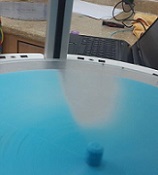
I have posted a bit about printing outside the triangle, near circles edge.
A lot of stuff changes there, some of which is fixable, some not so much.
Mainly inside the center triangle (all rods pointed in) errors in measurement are minimized by the geometry.
Outside the errors in measurement are multiplied. (see my avatar).
The big thing I can warn people off of, is using the z axis change when moving.
Typically, it might move up and down a half a millimeter, to avoid scraping the tops of the printed stuff.
It happens really fast. Big up and down jerk.
The problem comes when a rod is almost flat, printing near the edge of circle opposite a tower.
When its way out, any x-y move is multiplied by 10 times or more by the carriage opposite.
Even though the carriage can usually move fast, fast fast, combine
that with a quick jerk up and down, and I can get the belt to slip on the gear every time.
One it slips the zero is lost and the first layer is toast.
Solution(s)
1) Set acceleration much lower than default. I have it at about 200. No more jerks. Makes the whole prints a lot better, less "noise".
2) I just removed the Z axis hop, it had consistently worse results. If you like it, definitely lower the Z acceleration a LOT, I'd go below 100.
Too much mass to jerk the entire system up and down without slipping somewhere.
3) Slow it down, even with the above 2 items, the speed limit is for Cartesian X and Y, and not for the carriage movements.
If you print near the edge, you have to go a lot slower. Not just the first layer, but until you are high enough not to knock the
print loose from the surface.
Once the first layers are done, you can use the feed rate to increase speed a bit.
Something not to do, when making really wide prints.
Re: Something not to do, when making really wide prints.
I have problems with the bed leveling outside the triangle.
Are there any solutions for that? Like auto bed leveling with more then 4 points?
Are there any solutions for that? Like auto bed leveling with more then 4 points?
Re: Something not to do, when making really wide prints.
Well someone besides me is printing where dragons be.aehM_Key wrote:I have problems with the bed leveling outside the triangle.
Are there any solutions for that? Like auto bed leveling with more then 4 points?
Short answer is the older versions of software assume perfect physical geometry, and so no its not possible on them.
The latest firmware has some software to try and independently correct for small errors in tower position, rod length, and so with that version it will
get closer.
I developed my own, which was largely a duplicated effort.
However, mine recognizes a few more variables and gets closer, but takes longer to do. Maybe an hour or so.
I suggest get the latest version and use its software leveling procedure. If that doesn't work message me and I can get you a version
that will do calibration inside and outside the golden triangle.
Poor mans calibration, make a really thick first layer. 0.6 mm or so. It is close enough for lots of prints.
Re: Something not to do, when making really wide prints.
Oh, I forgot some stuff.
There are some un-calibratable errors you should check for with your hardware.
Using a carpenter square, double check the square on all towers. Not just kinda, but as close as you can get.
Square to the print bed. Ignore the roof.
If you have to adjust it, remember to take the tension off the belts first.
Put a small flashlight behind the square and shine it on the edge against the tower.
Move it up and down and look for variations.
There is such a thing as too tight, it will bow your tower.
See the G B N N post.
===========
Second check your parallelograms.
Unfortunately one step of the build process is sanding plastic parts. This determines how far apart the rod parallelograms are.
Check them with a caliper, and get them as close as you can. You can shim them with #4 washers.
You may need to sand more to get the shim in.
I posted a gcode circle to help test this, but you can just create a giant brim in slic3r too.
Check how a single layer does right next to each tower. If it prints evenly left center and right, the parallelograms are close enough.
If you have a bare spot one side and loose on the other, the long arms are different lengths (don't have a fix)
If you see loose spots on both sides, or bare spots on both sides, the sort arms are different lengths.
Adjust them as close as you can. The #4 washers make about a 0.8mm thick shim, so you should be able to get them
within half that to match. Its REALLY hard to measure accurately, so the flat circle print test is your best bet to test if its right.
Odds are there is some play in the parallelograms. See if any of the metal u joints can freely move back and forth on the steel rod.
Put a large rubber band around each pair, just tight enough that the rods cannot rattle freely back and forth.
best of luck
Re: Something not to do, when making really wide prints.
The latest firmware has some software to try and independently correct for small errors in tower position, rod length, and so with that version it will
get closer.
I am having this problem outside the triangle as well. Which software/firmware do you mean? Are there instructions for the software leveling procedure and/or variables to adjust other than the horizontal radius?I suggest get the latest version and use its software leveling procedure. If that doesn't work message me and I can get you a version
that will do calibration inside and outside the golden triangle.
This seems to be my problem, can software correct it?If you have a bare spot one side and loose on the other, the long arms are different lengths (don't have a fix)
Thanks
Re: Something not to do, when making really wide prints.
The latest repetier-firmware version has some calibration driven by "z-probing", which amounts to indicating when the head touches the surface at multiple points. (1.9x).
I believe that will get your printer as close as currently possible via software alone.
However, I believe most issues outside the triangle formed by the towers are hardware problems.
In particular the parallelogram errors are minimized near the center, and maximized near the edges.
My post suggests some ways to check your printers hardware.
1.9x also has some additional ability to calbrate, as it does not hard code each tower position and rod length, so with some work those errors can be calibrated out.
best of luck
Re: Something not to do, when making really wide prints.
This seems to be my problem, can software correct it?If you have a bare spot one side and loose on the other, the long arms are different lengths (don't have a fix)
Thanks[/quote]
Forgot to answer this part. The software only has a single number for rod length, so cannot help.
For my system I removed all the rods, then sorted them by length.
By length I mean hole to hole length.
Put a very small screwdriver in one end of a pair, and another in the opposite end.
Hold one level, the tilt of the other will indicate which is longer.
Once sorted, pair the longest two, middle two and shortest two.
It will minimize the error, but not entirely remove it.
Re: Something not to do, when making really wide prints.
Auto-calibration in Repetier-Firmware doesn't work. It never has for deltas.
g.
g.
Delta Power!
Defeat the Cartesian Agenda!
http://www.f15sim.com - 80-0007, The only one of its kind.
http://geneb.simpits.org - Technical and Simulator Projects
Defeat the Cartesian Agenda!
http://www.f15sim.com - 80-0007, The only one of its kind.
http://geneb.simpits.org - Technical and Simulator Projects
Re: Something not to do, when making really wide prints.
Not sure if we are talking about the same thing.
I am referring to z-probe calibration. It is not automatic.
You have to manually indicate contact by clicking a switch. (or by having an actual z-probe hookup)
The author of repetier-firmware uses this for his delta, so fairly sure it is only for deltas.
It will even correct for tilted prints surface.
I have been working with him aiding the software in some small ways, as i have time for it.
There are several different calibration commands, rather than give misinformation about details
I'd suggest people go to github.com/repetier, and see the repetier-firmware repository,
or follow the link to his site for instructions on using it, as I'm not proficient in that area.
Re: Something not to do, when making really wide prints.
I have NEVER seen a working auto-calibration for deltas outside work that's been done to a recent branch of Marlin. And yes, we're talking about the same thing - when the Z probe is used to touch a number of spots on the print surface. I'm not giving "misinformation" about anything. Also, auto-level != auto-calibration.
g.
g.
Delta Power!
Defeat the Cartesian Agenda!
http://www.f15sim.com - 80-0007, The only one of its kind.
http://geneb.simpits.org - Technical and Simulator Projects
Defeat the Cartesian Agenda!
http://www.f15sim.com - 80-0007, The only one of its kind.
http://geneb.simpits.org - Technical and Simulator Projects
Re: Something not to do, when making really wide prints.
Sorry if my comment was ambiguous, I meant I did not want to give misinformation myself, did not mean to imply you were.geneb wrote:I have NEVER seen a working auto-calibration for deltas outside work that's been done to a recent branch of Marlin. And yes, we're talking about the same thing - when the Z probe is used to touch a number of spots on the print surface. I'm not giving "misinformation" about anything. Also, auto-level != auto-calibration.
g.
Having said, I have had considerable communication with author on this subject, and he is definitely using his calibration method on his delta. It exists and was written for only for delta printers, as only delta printers in general are likely to have table tilt. The code is modified since 0.83 to allow for correction of tower position and delta rod length, which only appear on delta's. Beyond that I'd suggest anyone interested go to the source, which is not me.
Re: Something not to do, when making really wide prints.
How many iterations does it take to "solve" the bed and get perfectly parallel travel?
g.
g.
Delta Power!
Defeat the Cartesian Agenda!
http://www.f15sim.com - 80-0007, The only one of its kind.
http://geneb.simpits.org - Technical and Simulator Projects
Defeat the Cartesian Agenda!
http://www.f15sim.com - 80-0007, The only one of its kind.
http://geneb.simpits.org - Technical and Simulator Projects
Re: Something not to do, when making really wide prints.
I do not know. As I said I'm not the author, and am only aware it is out there.
As earlier posts I have made said, the software is not capable of correcting some of the hardware issues,
even the newest cannot deal with imperfect parallelogram arms.
As earlier posts I have made said, the software is not capable of correcting some of the hardware issues,
even the newest cannot deal with imperfect parallelogram arms.

Re: Something not to do, when making really wide prints.
Smoothie firmware does do delta calibration and I do mean all three tower z and the delta radius.
Takes some time for it to perform however as it goes through many iterations, testing and readjusting until all values are within 0.03 of each other.
Takes some time for it to perform however as it goes through many iterations, testing and readjusting until all values are within 0.03 of each other.
"Now you see why evil will always triumph! Because good is dumb." - Spaceballs
Re: Something not to do, when making really wide prints.
Is anyone running the smoothie firmware on here?Flateric wrote:Smoothie firmware does do delta calibration and I do mean all three tower z and the delta radius.
Takes some time for it to perform however as it goes through many iterations, testing and readjusting until all values are within 0.03 of each other.
Re: Something not to do, when making really wide prints.
me
"Now you see why evil will always triumph! Because good is dumb." - Spaceballs
Re: Beta simple calibration version
https://github.com/mrbi11/Repetier-Firmware" onclick="window.open(this.href);return false; is a rambo firmware with a direct calibration gcode, G100.mrbi11 wrote:I do not know. As I said I'm not the author, and am only aware it is out there.
As earlier posts I have made said, the software is not capable of correcting some of the hardware issues,
even the newest cannot deal with imperfect parallelogram arms.
See Direct-Calibrate.pdf for details.
Close calibration is near and dear, as I was trying to make much larger printed parts than is typical.
I contributed to the repetier-firmware. This beta will I hope be included in a future release.
Main differences it calibrated from end stops as a fixed point, instead of from a calculate maximum cartesian z axis height.
This simplifies a number of things.
The calibration is in 2 steps the first time, but no iterations.
Step 1, calibrate height of each tower (see doc), which amounts to moving the hot end in contact
with the surface in front of each tower (anywhere), and issuing "G100 X" for X, or Y or Z for those.
Step to, move to center, type G100 R, the radius is set.
If surface, surface temperature or hot end are remounted or changed, repeat step 1. You never have to repeat step 2.
I got closer matches to actual surface at z=0 with this than any amount of manual rcalibrating.
90% of area checkpoints were within +/-0.1mm. There are some "hot spots" of error at edges still, which get up to 0.3mm error,
but that is a hardware issue IMHO as described previous posts.
Feel free to try it and give feedback on results and on instructions in the doc. I'm no Shakespeare, so be kind.
Save your configuration.h, Do NOT use the configuration.h as released for Rostock, there is a second RostockMaxConfiguration.h in same folder.
You may want to merge in your favorite settings.
This presumes your print surface is square to your towers. If not, you need the leveling done in repetier's version, which does
an honest to god 3d rotation of the model as it prints. You will need to do some z-probing so his software can auto-calculate the surface slope.
If you have a speed square or carpenters square, its less brain work (for me) to just square up my printer.
last, the surface zero will change with heated bed temperature and hot end temperature slightly.
To re-zero after a temperature change do:
Move in contact with surface near middle
G100 x y z
Tada, all done
No iterating.
Good printing.
-
zachattack90
- Noob
- Posts: 1
- Joined: Sun Aug 31, 2014 5:34 pm
Re: Something not to do, when making really wide prints.
Hey, thanks for the G100 code guide! I'm going to try it once i get a chance tonight. I am new to the rostock community, as i recently built my first V2 about a week ago. After some calibration, the prints were putting the makerbot i previously used to shame! I'm not too sure what i did, perhaps it was too much weight being put on the filament extruder while i was trying to change colours, but ever since that moment i seem to have been plagued with the 'bed tilt' dilemma. I have tried to level the bottom of the machine with the top, I've tried compensating actual mechanical tower height by shifting the top plate up or down on one axis to see if it would eliminate the huge amount of lift I'm seeing in-between towers X and Z, whereas between towers X and Y it nearly pancakes the filament. Currently I've been achieving some decent but not show worthy prints by using small amounts of folded kapton tape underneath the wooden support for the onyx bed. It seems to be a tolerable, yet temporary solution in my eyes. I'm really hoping calibrating via G100 as you described will help me get back to printing! 
Quick question though, do you know if this is a common occurrence with the V2 or delta printers in general? And after calibrating and double checking the mechanical components to make sure every things tight, has anyone ever made any modifications to the printer chassis itself to ensure no tower torque/lean or anything? Thanks in advance!
Quick question though, do you know if this is a common occurrence with the V2 or delta printers in general? And after calibrating and double checking the mechanical components to make sure every things tight, has anyone ever made any modifications to the printer chassis itself to ensure no tower torque/lean or anything? Thanks in advance!
Re: Something not to do, when making really wide prints.
Remember the g100 is in beta version only. Its in line for release to main branch but not there yet.zachattack90 wrote:Hey, thanks for the G100 code guide! I'm going to try it once i get a chance tonight. I am new to the rostock community, as i recently built my first V2 about a week ago. After some calibration, the prints were putting the makerbot i previously used to shame! I'm not too sure what i did, perhaps it was too much weight being put on the filament extruder while i was trying to change colours, but ever since that moment i seem to have been plagued with the 'bed tilt' dilemma. I have tried to level the bottom of the machine with the top, I've tried compensating actual mechanical tower height by shifting the top plate up or down on one axis to see if it would eliminate the huge amount of lift I'm seeing in-between towers X and Z, whereas between towers X and Y it nearly pancakes the filament. Currently I've been achieving some decent but not show worthy prints by using small amounts of folded kapton tape underneath the wooden support for the onyx bed. It seems to be a tolerable, yet temporary solution in my eyes. I'm really hoping calibrating via G100 as you described will help me get back to printing!
Quick question though, do you know if this is a common occurrence with the V2 or delta printers in general? And after calibrating and double checking the mechanical components to make sure every things tight, has anyone ever made any modifications to the printer chassis itself to ensure no tower torque/lean or anything? Thanks in advance!
This gave me 9 kinds of fits trying to make a big flat print. The closest I can get is via the g100.
As for your machine, don't worry about the top, or level for that matter. Make sure the surface is square to the towers (columns)
with a carpenter square. From there calibrate with the g100.
You may need to loosen things a bit to adjust the tower tilt- it only has a tiny amount of play.
If you cant get square doing that shim the surface mounts.
I also have a mounting system i sell at me3d.us. It isn't more adjustable, but is less sensitive to glass temperature,
and not at all sensitive to the glass thickness, because it controls the height of the top of the surface,
not the height of the othe bottom of the insulator/heater. Expansion is downwards instead of upwards, and
it also is not prone to forming a dome shape. If you think you might be getting a dome (caused by heat xpanding in horizontal direction, but the edges are fixed in place)
you may want to try that.