Hi!
I just finished my Rostock Max some days ago and started with printing the Skeinforge Bridge Calibration Cube as recommended in the assembly manual. Apart from some slight gaps in the infill the machine seemed to work fine. But when I did a close inspection of the finished cube I found, that the view from above is out of square (it acutally looks almost like a parallelogram; I found that it is approximately 3-4 degrees out of right angle) and the four columns are approximately 0.5mm displaced. So I disassembled the whole carriage, reworked all the delta arm joints so that everything moves without friction. Then I printed the cube again - and the result was even worse. The second cube is even more out of square.
I did both prints with Repetier-Host V0.84 and Slic3r V0.9.8. All settings as recommended in the assembly manual. And I use the firmware from this page: https://github.com/johnoly99/Marlin-for ... kmax-rambo
Has anyone an idea what could cause this problem?
Thanks,
Sigi
Calibration Cube out of square

Re: Calibration Cube out of square
Pictures would be real helpful to see what the print looks like.
How stable are your cheapskates? Do they wobble at all? You should tighten the eccentric cams so they hold the cheapskate tight to the rail.
How stable are your cheapskates? Do they wobble at all? You should tighten the eccentric cams so they hold the cheapskate tight to the rail.
(No trees were killed to post this message, but a large number of electrons were terribly inconvenienced.)
Re: Calibration Cube out of square
The cheapskates are perfectly stable. I will take pictures of the cubes tomorrow morning.
Re: Calibration Cube out of square
Here are the pictures:
The only difference in printing was the speed. First print was 15mm/sec and second 30mm/sec.
The only difference in printing was the speed. First print was 15mm/sec and second 30mm/sec.
Re: Calibration Cube out of square
First off, see how that infill doesn't reach the inner walls. It absolutely looks like you have the delta arm blues. You need to remove your arms one by one and find the sticky spot and sand it down. You may have more than one. I only found 1 sticky arm on my printer, but it made a world of difference when I found it. Of course out of the 6 arms, it was the 5th arm I checked (on the Z rail) that was pretty stiff, I knew right away I found my issue.
Go back, try finding the sticky arm, fix it, and try printing some other calibration cubes. I suggest after fixing the arm (and printing a new test cube) - work on single wall calibration cubes next - make sure a single wall thickness is around 0.55 mm, if you get 1mm like me - you might have some settings in Slic3r (which aren't well covered without reading a lot of posts on the forums).
It can be daunting, but once you've gotten this printer calibrated, it's actually much nicer than other printers I've used since you don't need to constantly level the bed. (Or even worse - my replicator at work requires bed-leveling every time I switch between PLA and ABS because the bed's arms sag over 1mm at 90c!).
Good Luck!
(No trees were killed to post this message, but a large number of electrons were terribly inconvenienced.)
-
Polygonhell
- ULTIMATE 3D JEDI
- Posts: 2430
- Joined: Mon Mar 26, 2012 1:44 pm
- Location: Redmond WA
Re: Calibration Cube out of square
The fact the Skew is dependent on speed implies it's probably a sticky arm.
The friction is causing the head to lag behind the requested position, the faster you move the more it lags.
The friction is causing the head to lag behind the requested position, the faster you move the more it lags.
Printer blog http://3dprinterhell.blogspot.com/
Re: Calibration Cube out of square
Thank you for your answers.
I checked all the delta arms once more, but there are no signs of friction. If I connect the arms only to one u-joint they can swing freely like a pendulum. Just to be completely sure that there is no friction, I sanded the arms again. (Actually I think that this was not a good idea, because now I noticed that the whole carriage is a little loose - see video:
https://vimeo.com/63456919 )
However I tried to print the cube again (same settings from assembly manual as with first cube). I think it looks noticeably better and also the geometry errors are smaller. But when watching the printer building the infill areas I noticed, that the nozzle doesn't even travel over the areas where the gaps occur. Neither in longitudinal nor in transversal direction. I double-checked this behavior with the Z-Infill Calibration Thing several times and on various areas of the printing surface, but the result is always the same.
-
MorbidSlowBurn

- Printmaster!
- Posts: 169
- Joined: Sun Mar 03, 2013 5:33 pm
Re: Calibration Cube out of square
When you say your arms swing freely did you check in both directions? E.g. up and down or side to side.
The "side to side" swing is influenced by the pin to hole interface on the arms. This is corrected by "shaving" the hole on the arm.
The up and down is the Ujoint to carriage or cheapskate interfaces. This is corrected by sanding the inside of the arms.
The "side to side" swing is influenced by the pin to hole interface on the arms. This is corrected by "shaving" the hole on the arm.
The up and down is the Ujoint to carriage or cheapskate interfaces. This is corrected by sanding the inside of the arms.
Re: Calibration Cube out of square
They can swing freely in all directions. But as I tried to show in my video (https://vimeo.com/63456919) I think I've overdone it with widening the holes of the arms.
How to get rid of the delta arm blues
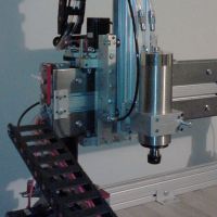
To finally get rid of the delta arm blues I built some new delta arms with ball bearrings and carbon fiber lamitate pipes. The spacers are made from aluminium pipes. So now I definitely have no more friction in any direction.
(You can also see improvements on the end stop adjustment screws so that they actuate the switches more reliably. I have attached the .stl file.)
To show if the effort was worth it, I will print the calibration cube again and post pictures asap, right now I am fighting with the LCD screen.
(You can also see improvements on the end stop adjustment screws so that they actuate the switches more reliably. I have attached the .stl file.)
To show if the effort was worth it, I will print the calibration cube again and post pictures asap, right now I am fighting with the LCD screen.
- Attachments
-
- endstopswitchring.stl
- (19.22 KiB) Downloaded 268 times
Re: Calibration Cube out of square
very nice, i'm going to be doing this to my rostock also as soon as the parts get here, what did you use to make yours?
My rostock build log http://forum.seemecnc.com/viewtopic.php?f=42&t=1228
-
Eaglezsoar

- ULTIMATE 3D JEDI
- Posts: 7185
- Joined: Sun Apr 01, 2012 5:26 pm
Re: Calibration Cube out of square
Very nice indeed! That is one of the nicest setups I have seen. It amazes me what people come up with and where they get those parts.
Great job! Could you give a source for those ball connectors. It looks like you used a different platform at the end of the arms also. Do you
have an STL for that? I know, we are all moochers, but hey its open source right? Thanks man.
Carl
Great job! Could you give a source for those ball connectors. It looks like you used a different platform at the end of the arms also. Do you
have an STL for that? I know, we are all moochers, but hey its open source right? Thanks man.
Carl
Re: Calibration Cube out of square
I got all the parts at our local model building store:
http://shop.lindinger.at/product_info.p ... anguage=en
The rest is a 3 mm steel wire, an aluminium pipe that fits over the steel wire to make the spacers, a 4 mm carbon fiber laminate tube, 12 pieces (45 mm each) of 4 mm threaded bar that I glued into the carbon fiber pipe with epoxy glue, some m4 nylon lock nuts nuts and 3 hours time.
Re: Calibration Cube out of square
Eaglezsoar wrote:Very nice indeed! That is one of the nicest setups I have seen. It amazes me what people come up with and where they get those parts.
Great job! Could you give a source for those ball connectors. It looks like you used a different platform at the end of the arms also. Do you
have an STL for that? I know, we are all moochers, but hey its open source right? Thanks man.
Carl
The platform is the original. I didn't make any changes.
Last edited by skyspy on Wed Apr 10, 2013 11:58 am, edited 1 time in total.
Re: Calibration Cube out of square
This is exactly what I wanted to do to mine.
How much slop is there in the system now (if any). My experience with those type of joint is they tend to have a little slop in them.
How is it working?
How much slop is there in the system now (if any). My experience with those type of joint is they tend to have a little slop in them.
How is it working?
"like, right now, 3D printing is in the DOS stages with the big black floppy disk OS"
Re: Calibration Cube out of square
The slop is less than 0.5 mm. This could probably be improved by putting some varnish on the 3 mm steel wire so that the ball connectors fit even more tightly and you can preselect the ball connectors (I have two that have a minimal slop.).
Re: Calibration Cube out of square
I just did a quick print of the bottom layers of the calibration cube with a new 0.35 mm nozzle. I think the settings are not optimal yet. The left with slic3r and the right one with kisslicer. The blob is from interrupting the printer.
Re: Calibration Cube out of square
What parts did you choose for your mod?cambo3d wrote:very nice, i'm going to be doing this to my rostock also as soon as the parts get here, what did you use to make yours?
"like, right now, 3D printing is in the DOS stages with the big black floppy disk OS"
-
Eaglezsoar
- ULTIMATE 3D JEDI
- Posts: 7185
- Joined: Sun Apr 01, 2012 5:26 pm
Re: Calibration Cube out of square
That's strange. That looks like what everyone is calling the Delta Arm Blues but that shouldn't be possible with your setup on the arms.
Please let us know when you figure out what settings you had too change.
Carl
Please let us know when you figure out what settings you had too change.
Carl
-
dsnettleton

- Printmaster!
- Posts: 102
- Joined: Fri Mar 22, 2013 11:09 am
Re: Calibration Cube out of square
I'm also interested to know what the problem is. I haven't been getting the infill I should be either, and I've also double-checked my delta arms.
Trust me, sir. I'm a wizard.
Re: Calibration Cube out of square
Here are my latest calibration prints. The wall is 0.54mm with a 0.5 nozzle and the infill on top of the cube also reaches the perimeters now.
Here is what I did:
1. I changed to Polygonhell's firmware. Much smoother movement of the stepper motors.
2. I used Cura for slicing.
3. I used a fan for cooling the print. That is how I got the walls straight.
Next I will try to print one of the more advanced calibration objects...
1. I changed to Polygonhell's firmware. Much smoother movement of the stepper motors.
2. I used Cura for slicing.
3. I used a fan for cooling the print. That is how I got the walls straight.
Next I will try to print one of the more advanced calibration objects...