
[img]http://farm9.staticflickr.com/8103/8568 ... 1ec818.jpg[/img]
Weekend update:
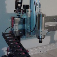
- Built the Extruder assembly - wow this thing is crazy over-engineered compared to my other 2 printers. Wish there was a higher def video or pictures of the build instructions - the video by SeeMeCNC is way too low resolution to be working with black parts - couldn't even see what was going on half the time! (Note, I have high resolution picts of the extruder assembly in my flickr account if anyone needs them)
- Installed the Steve's Extruder spacer (upgrade, purchaed from 3D Fabrication Works) - note the spacer MUST be installed AFTER the idler assembly has been installed, otherwise it won't sit properly (had to pull out the spacer after installing to make room for the ilder, then reinstall spacer)
- Sanded the CRAP out of the carriage and the arms - did the best I could, everything seems to be moving freely with no bumps that may cause issues later. Figurs after I was done and cleaned up from the sanding, I read the next step that tells me to sand the pieces for the cheapskates!
- At 16.3 of Geneb's manual, It says to use #6-32 x 1.75" machine screws, for the cheapskate fixed bearing side. I found these to be too short, and used the 2" screws instead. Hopefully I don't run low somewhere else!
- Cheapskates built, only 1 tightened completely, didn't have time to mess with the other two.
All that's left is to install the belts, endstops, wiring, hotbed, and LCD and I'll be ready to start calibrating (oh what fun that'll be)
Cassetti's black Rostock MAX build
Re: Cassetti's black Rostock MAX build
(No trees were killed to post this message, but a large number of electrons were terribly inconvenienced.)
Re: Cassetti's black Rostock MAX build
what's the link to your high res photos?
My rostock build log http://forum.seemecnc.com/viewtopic.php?f=42&t=1228
Re: Cassetti's black Rostock MAX build
http://www.flickr.com/photos/75376147@N ... 976583770/cambo3d wrote:what's the link to your high res photos?
(No trees were killed to post this message, but a large number of electrons were terribly inconvenienced.)
Re: Cassetti's black Rostock MAX build
[img]http://farm9.staticflickr.com/8366/8570 ... 9b9702.jpg[/img]
Daily update... man I wish I had taken off half of the week so I could have built this all at one time!
Didn't get too far last night.
- Tightened the cheapskate bearings. Don't know how but I missed tightening the axel support assembly before installing into the cheapskate, so I had to loosen up the screws and tighten down the support. Found one of the fixed bearings on the X axis was causing a bump bump bump effect on one particular bearing, swapped that bad one with the rear support bearing and the problem was resolved everything moved smooth as silk
- Installed print carriage arms into the cheapskates. Really not as bad as I expected. Simply twist the arms without fear of breaking them and you'll be fine - takes a few tries by all of them went in with little problem. Course the last arm took me a solid 5+ minutes to finally snap into place
- Installed and tensioned belts - I found it easiest to start at the bottom of the cheapskate, and thread it down the rail straight between the two idler bearings - this made it a chinch to fish. Then around the motor pulley, and up the front rail. Over the top idler pulley, and the only trouble spot was fishing it through the top of the cheapskate. I found a paperclip and patience worked best
- Installed endstop adjustment screws into U-joint carriers. Note there is only 1 hole for the adjustment screw on each U-joint carrier - of course on two of my carriers - the sheet metal screw that holds the rod in place enters into the hole used to hold the adjustment screw. I had to loosen 1 screw on 2 of the u-joint carriers in order to make space for the adjustment screw to fit properly into the hole - It took me 10 minutes to figure out why only 1 of the 3 adjustment screws went in so easily, the other 2 would never thread!) - Maybe Geneb's manual should be updated to mention the proper direction for the u-joint carriers
[img]http://farm9.staticflickr.com/8233/8570 ... 1fef4d.jpg[/img]
(Note the adjustment screw directly above the sheet metal screw - If I had flipped the u-joint carrier, I would have had plenty of depth to thread the adjustment screw)
At least it's starting to look like a delta 3D printer! Sounds like I'm going to have oodles of fun running the endstop wires tonight. I also expect tonight to begin my frustrating work of wiring up the printer. Wish the RAMBO had screw terminals instead of molex (dupont?) plugs. REALLY nervous about them - last time I had to crimp my own pins for connectors, I fried two printrboards.....
(No trees were killed to post this message, but a large number of electrons were terribly inconvenienced.)
-
MorbidSlowBurn

- Printmaster!
- Posts: 169
- Joined: Sun Mar 03, 2013 5:33 pm
Re: Cassetti's black Rostock MAX build
Cassetti- With the end stop screws I had no issue threading mine in and they are on the same side as you show. What length sheet metal screw did you use to retain the ujoint shaft? Sounds like they may have been a little long.
Re: Cassetti's black Rostock MAX build
Strange, not sure, whatever ones I was told to use (There was 1 bag with tiny sheet metal screws - 16 exactly, so i figured those were the ones I was supposed to use) - I guess I tightened too far - it seems they didn't really grab the rod - maybe that was the issue - I ended up adding a small washer to one side I had to loosen up so it would still grip the joint rod.... I think I may need to add 2 washers to account for how much I loosened the 2 screws. - They didn't completely enter the adjustment screw hole, but merely the tip was poking throughMorbidSlowBurn wrote:Cassetti- With the end stop screws I had no issue threading mine in and they are on the same side as you show. What length sheet metal screw did you use to retain the ujoint shaft? Sounds like they may have been a little long.
(No trees were killed to post this message, but a large number of electrons were terribly inconvenienced.)
Re: Cassetti's black Rostock MAX build
I believe there should have been two different lengths of the small sheet metal screws. The longer screws were for the hot end carriages and the slightly shorter screws were for the cheapskate bearing supports. On this weekend's build event, we saw the misplacement of the screws several times. The longer screws will cause interference with the limit screws. The lengths of these sheet metal screws are very similar and easy to get missed or swapped. My kit didn't include the smaller screws (or I dropped them of the table somewhere)
Re: Cassetti's black Rostock MAX build
I dont even see the need for two different sized sheet metal screws, they both work. I had the shorter screws on the cheapskates first but later after assembling the hotend, I found the shorter screws to be better for the hot end because they dont stick out and give it a clean look. So I swapped them around. Longer ones do interfere with the limit screw so a short screw would be necessary here.
but really all they need to include is the shorter sheet metal screws to cover the hotend and the cheapskates.
but really all they need to include is the shorter sheet metal screws to cover the hotend and the cheapskates.
My rostock build log http://forum.seemecnc.com/viewtopic.php?f=42&t=1228
Re: Cassetti's black Rostock MAX build
cambo3d wrote:I dont even see the need for two different sized sheet metal screws, they both work. I had the shorter screws on the cheapskates first but later after assembling the hotend, I found the shorter screws to be better for the hot end because they dont stick out and give it a clean look. So I swapped them around. Longer ones do interfere with the limit screw so a short screw would be necessary here.
but really all they need to include is the shorter sheet metal screws to cover the hotend and the cheapskates.
Thanks, I was worried I'd have to remove all of the screws. I bet that's what happened - I used the short screws for my carriage
(No trees were killed to post this message, but a large number of electrons were terribly inconvenienced.)
Re: Cassetti's black Rostock MAX build
Cassetti,
From the looks of it, you ended up using the longer screws when installing the idler rollers in the base here:
[img]http://farm9.staticflickr.com/8374/8554 ... 65c5_z.jpg[/img]
Just thought I would give you a heads up on it while I was browsing.
From the looks of it, you ended up using the longer screws when installing the idler rollers in the base here:
[img]http://farm9.staticflickr.com/8374/8554 ... 65c5_z.jpg[/img]
Just thought I would give you a heads up on it while I was browsing.
Re: Cassetti's black Rostock MAX build
Hmm, looks like you're right, darn, hope that isn't a big woopsrobstah wrote:Cassetti,
From the looks of it, you ended up using the longer screws when installing the idler rollers in the base here:
[img]http://farm9.staticflickr.com/8374/8554 ... 65c5_z.jpg[/img]
Just thought I would give you a heads up on it while I was browsing.
(No trees were killed to post this message, but a large number of electrons were terribly inconvenienced.)
Re: Cassetti's black Rostock MAX build
[img]http://farm9.staticflickr.com/8522/8575 ... 77d0df.jpg[/img]
Update on the build - haven't gotten much accomplished
* For some reason I had to install my endstops in the position shown because the adjustment screws weren't hitting the end of the switch properly.
* Ran wires for endstops through the rails - boy was that a pain! I tried the twist method of twisting the wires together, but I still couldn't manage to get them through the rails. The fishing line trick worked great, though I think heavier fishing line would have been a better bet
* Tested my new crimping tool (http://www.amazon.com/HT-225D-Cycle-Rat ... B007JLN93S) on one of the motors. Holy crap, finally molex (dupont) plugs are no problem! I spent 3 DAYS crimping the molex pins by hand with a pair of pliers for my Prusa i2, only to fry two control boards because I didn't have the right tool for the job!
No longer worried about crimping pins to wire up the machine. Tonight I'll be soldering the LCD adapter, and the Hotbed. Although I think I might buy a new soldering iron for those, don't think mine is the best for the job (Weller butane "portosol" iron).
Last edited by cassetti on Thu Mar 21, 2013 9:32 am, edited 1 time in total.
(No trees were killed to post this message, but a large number of electrons were terribly inconvenienced.)
Re: Cassetti's black Rostock MAX build
having the right tool, makes a big difference.
My rostock build log http://forum.seemecnc.com/viewtopic.php?f=42&t=1228

Re: Cassetti's black Rostock MAX build
You mentioned vice grips to put (hex nuts) nylocks into the boards.
PartsDaddy had a hip tip - to take needle nose and hold them at a 45 degree angle and roll them in. After doing that, putting them in was almost fool-proof. There were a couple that required a bigger tool but overall, it worked great.
PartsDaddy had a hip tip - to take needle nose and hold them at a 45 degree angle and roll them in. After doing that, putting them in was almost fool-proof. There were a couple that required a bigger tool but overall, it worked great.
Technologist, Maker, Willing to question conventional logic
http://dropc.am/p/KhiI1a" onclick="window.open(this.href);return false;
http://dropc.am/p/KhiI1a" onclick="window.open(this.href);return false;
Re: Cassetti's black Rostock MAX build
Interesting, I managed to get most of mine in with no problem, I only had trouble with 2 or maybe 3 into the boards. Of course with my luck, the first hex nut I installed was in a tight slot, making me worried I'd have this issue with all slots. Nope, only a few, the rest were fine (a few were so loose I had to wait until just before installing the panel to place the nut, otherwise I'd fall right out!JohnStack wrote:You mentioned vice grips to put (hex nuts) nylocks into the boards.
PartsDaddy had a hip tip - to take needle nose and hold them at a 45 degree angle and roll them in. After doing that, putting them in was almost fool-proof. There were a couple that required a bigger tool but overall, it worked great.
(No trees were killed to post this message, but a large number of electrons were terribly inconvenienced.)
Re: Cassetti's black Rostock MAX build
[img]http://farm9.staticflickr.com/8247/8578 ... 3097c3.jpg[/img]
* Finished soldering everything to the Onyx, installed the aluminum heat spreader (purchased from mhackney's store) on top. Check that one off the list, woot!
* Soldered my PCB adapter for the LCD screen. Bought a new variable temp Weller 40watt iron with a chisel tip, did a pretty good job. Looks like I got all the connections good enough, considering I've only soldered anything to a pcb only a handful of times in my life.....
[img]http://farm9.staticflickr.com/8371/8578 ... 6cc43c.jpg[/img]
* Examined mounting the LCD panel when I noticed the LCD door was upside down and backwards!! Sonofa..... I ended up deciding to rest the printer upside down (yikes!) and loosen the screws on the base plate around the door. Took a bit of effort and some knicked up wood, but I got it out and flipped around. What I thought would be a catastrophic event, wasn't so bad, maybe 5 minute setback. phew!
[img]http://farm9.staticflickr.com/8245/8579 ... f30f46.jpg[/img]
Despite my experience and soldering practice extending the Z motor wires and the PCB connectors with this new iron, I somehow managed to melt the center pin of the power switch, thereby shorting the switch! Of all the things to mess up on, it was a simple/cheap power switch
  - phew, thank god. I contacted support to see if I can get a replacement for that, but in the meantime I had a spare toggle switch to get me by for now, but I'd rather install the original switch.
Another hour or so tonight to connect the hotend wires, and this printer will be ready for final assembly! Finally, I have a whole weekend to power up the machine and start calibrating it!
Does anyone have a link to a manual or pictures of installing the LCD screen at an angle? I can't figure out how the lcd mounts to the angle brackets.
* Finished soldering everything to the Onyx, installed the aluminum heat spreader (purchased from mhackney's store) on top. Check that one off the list, woot!
* Soldered my PCB adapter for the LCD screen. Bought a new variable temp Weller 40watt iron with a chisel tip, did a pretty good job. Looks like I got all the connections good enough, considering I've only soldered anything to a pcb only a handful of times in my life.....
[img]http://farm9.staticflickr.com/8371/8578 ... 6cc43c.jpg[/img]
* Examined mounting the LCD panel when I noticed the LCD door was upside down and backwards!! Sonofa..... I ended up deciding to rest the printer upside down (yikes!) and loosen the screws on the base plate around the door. Took a bit of effort and some knicked up wood, but I got it out and flipped around. What I thought would be a catastrophic event, wasn't so bad, maybe 5 minute setback. phew!
[img]http://farm9.staticflickr.com/8245/8579 ... f30f46.jpg[/img]
Despite my experience and soldering practice extending the Z motor wires and the PCB connectors with this new iron, I somehow managed to melt the center pin of the power switch, thereby shorting the switch!
Another hour or so tonight to connect the hotend wires, and this printer will be ready for final assembly! Finally, I have a whole weekend to power up the machine and start calibrating it!
Does anyone have a link to a manual or pictures of installing the LCD screen at an angle? I can't figure out how the lcd mounts to the angle brackets.
(No trees were killed to post this message, but a large number of electrons were terribly inconvenienced.)
-
Eaglezsoar

- ULTIMATE 3D JEDI
- Posts: 7185
- Joined: Sun Apr 01, 2012 5:26 pm
Re: Cassetti's black Rostock MAX build
Cambo3D's build contains the best pictures of how he mounted the LCD at an angle. That's probably the best source that I have seen.
I like it when someone posts pictures of their mistakes, it helps the rest of us not repeat the same. Besides it's kinda cool to see the words
Light and Power upside down, that one gave me a good chuckle. Good job fixing it without major dis-assembly.
Carl
I like it when someone posts pictures of their mistakes, it helps the rest of us not repeat the same. Besides it's kinda cool to see the words
Light and Power upside down, that one gave me a good chuckle. Good job fixing it without major dis-assembly.
Carl
Re: Cassetti's black Rostock MAX build
Thanks, I'll check it out
(No trees were killed to post this message, but a large number of electrons were terribly inconvenienced.)
Re: Cassetti's black Rostock MAX build
Finishing up the final assembly tonight, powering up tomorrow afternoon!
I have been looking all over, but I still can't find any info on how to physically mount the LCD panel to the standoffs - I have seen pictures of the standoff's in their proper mounting position, and the lcd panel mounted, but there are no screw holes that match up wth the panel itself...
Edit, now it appears to be a ressure fit, but then how does the wood panel fit? How is that secured?
Also I just noticed my LCD cables don't reach from the LCD door to the electronics door! Guess that means I need to move the Rambo board, any suggestions where to move it? I assume it must be mounted on the LCD door?
Last edited by cassetti on Fri Mar 22, 2013 11:05 pm, edited 1 time in total.
(No trees were killed to post this message, but a large number of electrons were terribly inconvenienced.)
Re: Cassetti's black Rostock MAX build
cassetti wrote:Finishing up the final assembly tonight, powering up tomorrow afternoon!
I have been looking all over, but I still can't find any info on how to physically mount the LCD panel to the standoffs - I have seen pictures of the standoff's in their proper mounting position, and the lcd panel mounted, but there are no screw holes that match up wth the panel itself...
My rostock build log http://forum.seemecnc.com/viewtopic.php?f=42&t=1228
Re: Cassetti's black Rostock MAX build
Thanks, but how does the wood face plate mount? The holes that match up are covered by the standoff
And my lcd cables are too short - need to find a new mounting position
And my lcd cables are too short - need to find a new mounting position
Last edited by cassetti on Sat Mar 23, 2013 5:29 pm, edited 1 time in total.
(No trees were killed to post this message, but a large number of electrons were terribly inconvenienced.)
Re: Cassetti's black Rostock MAX build
i drilled holes in it to match the holes in the lcd, then screw the faceplate on through the mount and into the lcd holes.
If you do this, be careful not to split the angle standoffs, get them aligned as best u can so all your holes will line up.
there are small 4-40 phillips screws included for mounting the faceplate.
If you do this, be careful not to split the angle standoffs, get them aligned as best u can so all your holes will line up.
there are small 4-40 phillips screws included for mounting the faceplate.
My rostock build log http://forum.seemecnc.com/viewtopic.php?f=42&t=1228
Re: Cassetti's black Rostock MAX build
I was afraid of thatcambo3d wrote:i drilled holes in it to match the holes in the lcd, then screw the faceplate on through the mount and into the lcd holes.
If you do this just have to be careful not to split the angle standoffs, get them aligned as best u can so all your holes will line up.
there are small 4-40 phillips screws included for mounting the faceplate.
(No trees were killed to post this message, but a large number of electrons were terribly inconvenienced.)
Re: Cassetti's black Rostock MAX build
yeah not my favorite design either. They should have the lcd mounted to the faceplate. Then make a standoff that mounts the faceplate to the door.
My rostock build log http://forum.seemecnc.com/viewtopic.php?f=42&t=1228
-
foshon

- Printmaster!
- Posts: 605
- Joined: Fri Mar 08, 2013 3:05 pm
- Location: Just to the right of SeeMeCNC
Re: Cassetti's black Rostock MAX build
cambo3d wrote:yeah not my favorite design either. They should have the lcd mounted to the faceplate. Then make a standoff that mounts the faceplate to the door.
I did mine a little differently, I used the bottom two holes that the lcd would mount to if you put it flat in the door. I had to drill them out, but the standoffs then slide over the board holding it in place. If I can get flickr to let me upload, I'll post pics.
Purple = sarcasm
Please do a board search before posting your question, many have been answered with very time consuming detail already.
Please do a board search before posting your question, many have been answered with very time consuming detail already.