
Proceeding on to the wiring. First the Onyx heated bed. I measured the length of the wires from the bed to the RAMBo to be a generous 18". So I cut the 2 white wires with connector to 18" and soldered the leads to the bottom of the onyx. Polarity does not matter on this connection.
I've learned from my H-1 experience that it is not good to skimp on the high current wiring to the hot bed and hot end! The Onyx draws 10Amps at 12 Volts so I used two 18 Gauge wires to each pad - this is wire that I already had, it did not come in the kit. Polarity does matter so make sure to connect the black wires to (-) and red to (+) (or whatever colors you are using for + and -) to the underside of the bed.
[img]http://mhackney.zenfolio.com/img/s8/v79 ... 6614-3.jpg[/img]
The wires pass through the slot near the Z axis. The spacers and screws to mount the bed were included.
[img]http://mhackney.zenfolio.com/img/s8/v81 ... 5700-3.jpg[/img]
The plastic spacers goes between the table and the Melamine "snowflake" spacer. They provide the clearance need to route the wires underneath and through the slot. Now seeing how the slot relates to the solder pads on the Onyx, I would turn the wires around so they point to the middle of the Onyx. The opposite of what I show above.
[img]http://mhackney.zenfolio.com/img/s1/v49 ... 5654-3.jpg[/img]
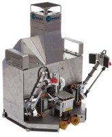
Here is the heated bed mounted and ready to go. I've placed the piece of custom cut glass on so you can see that too.
[img]http://mhackney.zenfolio.com/img/s1/v47 ... 7034-3.jpg[/img]
Mhackney's Rostock Max
Onyx Wiring
Sublime Layers - my blog on Musings and Experiments in 3D Printing Technology and Art
Start Here:
A Strategy for Successful (and Great) Prints
Strategies for Resolving Print Artifacts
The Eclectic Angler
Hot End Setup and Wiring
Next up is the hot end. I have the newest (as of 2/1/2013) hot end and it is a little different than the one shown in the manual.
First, install the Hot End Adapter Plate #68328 and Hot End Spacer #68324. Note that the new hot end (or at least mine) has a steel hex nut rather than a knurled aluminum nut. Be very careful not to cross thread or over-tighten when installing this nut - I went finger tight.
[img]http://mhackney.zenfolio.com/img/s8/v77 ... 5172-3.jpg[/img]
Then install the Bowden Fitting - tightening it enough to compress the rubber O ring to get a good seal.
[img]http://mhackney.zenfolio.com/img/s8/v79 ... 5256-3.jpg[/img]
Here's a close-up of the new nozzle. Note how low it sits to the hot end. It is too tight to install with just finger pressure so use a wrench - but carefully.
[img]http://mhackney.zenfolio.com/img/s8/v13 ... 5346-3.jpg[/img]
Heat is supplied to the hot end with two big resistors. Current passing through these causes them to heat up (a lot!). A few points on these resistors:
[img]http://mhackney.zenfolio.com/img/s3/v45 ... 5820-3.jpg[/img]
Wrap tightly, checking fit in the hot end. Add as much foil as you need to get a snug fit. Note that the foil is well away from the leads.
[img]http://mhackney.zenfolio.com/img/s8/v83 ... 5924-3.jpg[/img]
Insert the resistors and double check that the foil does not touch the leads. Then, dab high temp silicone in place with a toothpick to completely seal around the lead and fill the opening at each end.
[img]http://mhackney.zenfolio.com/img/s8/v74 ... 6554-3.jpg[/img]
This does several things - it holds the resistors in place, insulates the ends to keep heat in the hot end, and it electrically insulates the leads from the aluminum hot end.
Next, install the thermistor in the little hole between the two resistors. I separate the leads so they are not shorted, place a blob of silicone on the thermistor and about 1/8" of the leads, and then squish it in to the hole.
[img]http://mhackney.zenfolio.com/img/s8/v74 ... 6728-3.jpg[/img]
At this point, set the hot end aside until the silicone is COMPLETELY cured! In my impatience in the past, I only waited 4 or 5 hours and that was not enough time. The thermistor and/or resistors pulled out. It is much better to do it once and do it right!
NOTE: I am going to update the first post in this thread to recommend assembling the hot end first and setting aside. That will ensure that the silicone has cured properly. As it is, I'll wait until tomorrow, at least, before touching it.
First, install the Hot End Adapter Plate #68328 and Hot End Spacer #68324. Note that the new hot end (or at least mine) has a steel hex nut rather than a knurled aluminum nut. Be very careful not to cross thread or over-tighten when installing this nut - I went finger tight.
[img]http://mhackney.zenfolio.com/img/s8/v77 ... 5172-3.jpg[/img]
Then install the Bowden Fitting - tightening it enough to compress the rubber O ring to get a good seal.
[img]http://mhackney.zenfolio.com/img/s8/v79 ... 5256-3.jpg[/img]
Here's a close-up of the new nozzle. Note how low it sits to the hot end. It is too tight to install with just finger pressure so use a wrench - but carefully.
[img]http://mhackney.zenfolio.com/img/s8/v13 ... 5346-3.jpg[/img]
Heat is supplied to the hot end with two big resistors. Current passing through these causes them to heat up (a lot!). A few points on these resistors:
- The leads must not touch any other metal items like the hot end barrel or a short circuit might occur. There is a lot of current passing through these and a short would be BAD.
- The resistors must have good thermal contact with the hot end. They are much smaller in diameter than the holes provided for them. The extra space is filled in with aluminum foil as described below.
[img]http://mhackney.zenfolio.com/img/s3/v45 ... 5820-3.jpg[/img]
Wrap tightly, checking fit in the hot end. Add as much foil as you need to get a snug fit. Note that the foil is well away from the leads.
[img]http://mhackney.zenfolio.com/img/s8/v83 ... 5924-3.jpg[/img]
Insert the resistors and double check that the foil does not touch the leads. Then, dab high temp silicone in place with a toothpick to completely seal around the lead and fill the opening at each end.
[img]http://mhackney.zenfolio.com/img/s8/v74 ... 6554-3.jpg[/img]
This does several things - it holds the resistors in place, insulates the ends to keep heat in the hot end, and it electrically insulates the leads from the aluminum hot end.
Next, install the thermistor in the little hole between the two resistors. I separate the leads so they are not shorted, place a blob of silicone on the thermistor and about 1/8" of the leads, and then squish it in to the hole.
[img]http://mhackney.zenfolio.com/img/s8/v74 ... 6728-3.jpg[/img]
At this point, set the hot end aside until the silicone is COMPLETELY cured! In my impatience in the past, I only waited 4 or 5 hours and that was not enough time. The thermistor and/or resistors pulled out. It is much better to do it once and do it right!
NOTE: I am going to update the first post in this thread to recommend assembling the hot end first and setting aside. That will ensure that the silicone has cured properly. As it is, I'll wait until tomorrow, at least, before touching it.
Sublime Layers - my blog on Musings and Experiments in 3D Printing Technology and Art
Start Here:
A Strategy for Successful (and Great) Prints
Strategies for Resolving Print Artifacts
The Eclectic Angler
Houston, we have movement!
Finished wiring everything except the hot end - which I will leave for the silicone to cure overnight.
I used the default Marilin firmware that came with my RAMBo.
I then opened Repetier Host Mac 0.52 and configured a new printer:
Printer Settings
Port: usbmodem1411
Baud Rate: 250000
Stop Bits: 1
Parity: None
Transfer Protocol: Auto Detect
Receive cache size: 63
Dimension
280
280
350
XMin = YMin = -140
XMax = YMax = 140
Bed Left = Bed Front = -140
Then I connected to the printer - all OK! Then I checked the limit switches as per the manual, that worked. Then I homed each axis individually. Each axis moved up, homed and stopped! Very cool watching this thing move.
That's when things went amiss! I can not move the axis by clicking the incremental move buttons. I get a "Printer stopped deu to errors." (misspelling and all!) error. Perhaps this is because the firmware is not configured for my machine but that is odd given the home buttons worked. I also get no movement when I issue a G0 or G1 command to move an axis.
Also, my hot bed seems not to heat up. Agin, could be a firmware issue.
My preference is to run the Repetier firmware so I am going to go down that route and see what happens then.
Cheers,
Michael
Sublime Layers - my blog on Musings and Experiments in 3D Printing Technology and Art
Start Here:
A Strategy for Successful (and Great) Prints
Strategies for Resolving Print Artifacts
The Eclectic Angler
Repetier Firmware
Ok, I grabbed the Repetier firmware that Halopend posted. Fired up the Arduino 1.0.3 on my Mac, loaded it, turned off using the EEPROM (so I can tweak/control completely from the code for now), compiled and uploaded.
Then I connected in Repetier host and the 3 axis work properly! I can jog around and home. However, Z axis jogging is painfully slow. I looked through the Configuration.h file and all 3 axis have the same MAX feedrate. I presume that applies to the individual axes motor - which are labeled X, Y and Z but are not actually cartesian coordinates. Is conversion from delta to cartesian lowering the federate? I have no experience with delta printers but I'll browse around in the code and see what I can see.
The heated bed is still not working. However, I do not have my hotend or hotend thermistor hooked up so maybe that fault is preventing the heated bed control from working.
Sublime Layers - my blog on Musings and Experiments in 3D Printing Technology and Art
Start Here:
A Strategy for Successful (and Great) Prints
Strategies for Resolving Print Artifacts
The Eclectic Angler
-
Eaglezsoar

- ULTIMATE 3D JEDI
- Posts: 7159
- Joined: Sun Apr 01, 2012 5:26 pm
Re: Mhackney's Rostock Max
I can't help you with your problem but I have a Rostock Max that I haven't built yet and I want to run repitier firmware and host. After reading through this entire thread I get the impression that everyone is using a version of Mac OS or Ubuntu. Is there
anyone on this thread who is using Windows?
anyone on this thread who is using Windows?
Re: Mhackney's Rostock Max
I'm sure people are using Windows! The Repetier Host for Windows has a great new feature to support a round build plate. The Mac version doesn't support that yet.
Sublime Layers - my blog on Musings and Experiments in 3D Printing Technology and Art
Start Here:
A Strategy for Successful (and Great) Prints
Strategies for Resolving Print Artifacts
The Eclectic Angler
Music!
My son just came over to watch the Rostock Max "dry printing" an object. He said it sounds like bagpipes playing! It does! Here's a short video.
[youtube]http://www.youtube.com/watch?v=vSN_sRuatsI[/youtube]
cheers,
Michael
[youtube]http://www.youtube.com/watch?v=vSN_sRuatsI[/youtube]
cheers,
Michael
Sublime Layers - my blog on Musings and Experiments in 3D Printing Technology and Art
Start Here:
A Strategy for Successful (and Great) Prints
Strategies for Resolving Print Artifacts
The Eclectic Angler
Heated Bed debugging?
I'm trying to determine why my heated bed (Onyx) is not working. I checked the output at the heated bed connector on the RAMBo and with the Heat On and temp set to 55°C I am not getting any power. I switched from PID to Bam-Bam control in the firmware and still nothing. And yes, I did make sure HAVE_HEATED_BED is true. This is Repetier Firmware as downloaded from Halopend. HEATER_BED_PIN for RAMBo in pins.h is set to 3.
I also checked the 15 amp fuse, it is ok and I attempted to measure voltage across it when the heater should be active - no volts measured. I have measured 12V at the heated bed power input block.
And, I do seem to be getting a temp measurement on the heated bed thermistor - of I place my finger over it for a few seconds, I see the heat rise.
Anyone have any suggestions?
thanks,
Michael
Sublime Layers - my blog on Musings and Experiments in 3D Printing Technology and Art
Start Here:
A Strategy for Successful (and Great) Prints
Strategies for Resolving Print Artifacts
The Eclectic Angler
Re: Mhackney's Rostock Max
I'm not sure with this, but I think you have to hook up your hotend thermistor.
-
Polygonhell
- ULTIMATE 3D JEDI
- Posts: 2417
- Joined: Mon Mar 26, 2012 1:44 pm
- Location: Redmond WA
Re: Mhackney's Rostock Max
if there is voltage and the pin is being set in the firmware, you should see an LED come on when you turn the bed on.
If you see an LED and there is no power to the bed, it's most likely that your firmware is configured for the wrong output, if this is the case DO NOT under any circumstances plug the bed into a different input, it will blow the fuse on the board.
If it's not that and you have 12V on all of the inputs to the board, you're pretty much reduced to following the circuit, with one end of the meter connected to ground and the other measuring voltage. The heated bed circuit is fairly simple, basically just the fuse, a mosfet and the arduino pin, just don't short anything with the probe.
Printer blog http://3dprinterhell.blogspot.com/
Re: Mhackney's Rostock Max
There is no voltage at the output terminal to the heated bed. There is 12V at the power input terminal. The LED does not come on - there is no power going to the bed. Firmware configured for pin 3 for heated bed output. This is correct according to the RAMBo pinout table.
Sublime Layers - my blog on Musings and Experiments in 3D Printing Technology and Art
Start Here:
A Strategy for Successful (and Great) Prints
Strategies for Resolving Print Artifacts
The Eclectic Angler
Heated Bed Output - Important Tip!
Gentleman, my and aehM_Key's suspicions were indeed correct - the hotend thermistor MUST BE connected (or perhaps disabled in firmware) in order for the heated bed circuitry to be enabled. Not sure where this is in the code but now that I know this is the case I'll look for it.
So, at this point, my heated bed is working fine! And it heats up quickly too, this power supply rocks. Less than 4 1/2 minutes to get to 85°C and that was with 2 ramps - 60° first and then up to 80°.
[img]http://mhackney.zenfolio.com/img/s8/v79 ... 2032-3.jpg[/img]
So, at this point, my heated bed is working fine! And it heats up quickly too, this power supply rocks. Less than 4 1/2 minutes to get to 85°C and that was with 2 ramps - 60° first and then up to 80°.
[img]http://mhackney.zenfolio.com/img/s8/v79 ... 2032-3.jpg[/img]
Sublime Layers - my blog on Musings and Experiments in 3D Printing Technology and Art
Start Here:
A Strategy for Successful (and Great) Prints
Strategies for Resolving Print Artifacts
The Eclectic Angler
Hot End Wiring
As reported in the last post, the hot end thermistor must be hooked up in order for the hot bed to work.
I used crimp connectors for the heating resistors. Don't solder these connections, they will fail and you'll have a mess if your lucky and short circuit and/or fire if not. Don't ask... (H-1 experience). I routed the wiring through the adapter plate.
[img]http://mhackney.zenfolio.com/img/s8/v83 ... 6452-3.jpg[/img]
I like to use thin wall small diameter teflon tubing (McMaster) to insulate the thermistor leads. It is just as important to have a solid connection on the terminator. If the leads break or disconnect during a run, the feedback loop will be broken and the RAMBo will continue to pump current to the hot end until it melts down. Don't ask...
[img]http://mhackney.zenfolio.com/img/s8/v77 ... 6142-3.jpg[/img]
I put a blob of silicone over the silicone holding the thermistor in place then push the ends of the teflon into that to secure them. Leave about 1/4" to 3/8" of lead exposed. I put a short (3/4") length of heat shrink tube over each of the teflon tubes and solder the white wires to the leads. Then I shrink the tube over the teflon tube and solder joint to make a clean, insulated connection.
[img]http://mhackney.zenfolio.com/img/s1/v47 ... 6284-3.jpg[/img]
I'll let the silicone cure overnight before testing the hot end. I've learned that it pays to be patient and let the the silicone cure on the hotend before pushing ahead! This is the one area of the build where bad things can happen if the connections fail or short.
cheers,
Michael
Sublime Layers - my blog on Musings and Experiments in 3D Printing Technology and Art
Start Here:
A Strategy for Successful (and Great) Prints
Strategies for Resolving Print Artifacts
The Eclectic Angler
Re: Mhackney's Rostock Max
I'm glad it worked out for you.
Is there any reason, why I shouldn't use the two remaining wires of the 4 conductor 18ga wire for the thermistor? (I'm not going to add a second hotend or LEDs.)
Is there any reason, why I shouldn't use the two remaining wires of the 4 conductor 18ga wire for the thermistor? (I'm not going to add a second hotend or LEDs.)
Re: Mhackney's Rostock Max
No reason at all, go ahead! I did this on my H-1. However, I did end up adding a fan to that and I plan to add a fan to mine. If you are planning to print with PLA you'll need one.
Sublime Layers - my blog on Musings and Experiments in 3D Printing Technology and Art
Start Here:
A Strategy for Successful (and Great) Prints
Strategies for Resolving Print Artifacts
The Eclectic Angler
All wired up and ready to calibrate
Finished off the wiring to the hot end and extruder stepper this morning during the raging blizzard! Tested heating the bed, hot end and moving all the steppers. Everything is ready to go!
Sublime Layers - my blog on Musings and Experiments in 3D Printing Technology and Art
Start Here:
A Strategy for Successful (and Great) Prints
Strategies for Resolving Print Artifacts
The Eclectic Angler
Z Axis movement question
When I home and then go to Z=0, the nozzle ends up about 181mm from the bed. Almost exactly 1/2 of the full travel of the Z for the Rostock. My configuration.h has:
#define X_MAX_LENGTH 363.0
#define Y_MAX_LENGTH 363.0
#define Z_MAX_LENGTH 363.0
8 microsteps on all axes.
Without measuring (eyeballing) X and Y seem to be traveling the right amount. A G0 X10 movement looks pretty darned close to 10mm. I'm very familiar with calibrating cartesian printers and I verified everything in configuration.h (I have eeprom disabled for now and verified that too). Given that X and Y move the correct amount, that tells me that all 3 delta axes are in the ballpark. So I have no idea why or what to do about Z moving half as far as it is told. Any suggestions? This is using the Repetier firmware that Halopend posted recently.
Regards,
Michael
Sublime Layers - my blog on Musings and Experiments in 3D Printing Technology and Art
Start Here:
A Strategy for Successful (and Great) Prints
Strategies for Resolving Print Artifacts
The Eclectic Angler
All axes are moving 1/2 as far
Well, I actually measured a 10mm movement in X and Y and it appears that they are only moving 1/2 the distance too (about 5mm).
So, the issue seems to be on all 3 axes. I enabled eeprom so I could verify settings. I've attached a screenshot here. Does anyone notice anything odd? It looks fine to me.
So, the issue seems to be on all 3 axes. I enabled eeprom so I could verify settings. I've attached a screenshot here. Does anyone notice anything odd? It looks fine to me.
Sublime Layers - my blog on Musings and Experiments in 3D Printing Technology and Art
Start Here:
A Strategy for Successful (and Great) Prints
Strategies for Resolving Print Artifacts
The Eclectic Angler
Problem solved!
Turns out that the 1.1 Rev of the RAMBo is 16 micro steps. I don't know how long this version has been out but it is what came with my kit. Simply changing:
#define MICRO_STEPS 16
in configuration.h solved the problem and I am now working on calibration.
#define MICRO_STEPS 16
in configuration.h solved the problem and I am now working on calibration.
Sublime Layers - my blog on Musings and Experiments in 3D Printing Technology and Art
Start Here:
A Strategy for Successful (and Great) Prints
Strategies for Resolving Print Artifacts
The Eclectic Angler
-
Eaglezsoar
- ULTIMATE 3D JEDI
- Posts: 7159
- Joined: Sun Apr 01, 2012 5:26 pm
Re: Problem solved!
What value should be in there?mhackney wrote:Turns out that the 1.1 Rev of the RAMBo is 16 micro steps. I don't know how long this version has been out but it is what came with my kit. Simply changing:
#define MICRO_STEPS 16
in configuration.h solved the problem and I am now working on calibration.
I assume it should be 8 but I need to be sure.
Re: Mhackney's Rostock Max
for rev 1 it is 8 for rev 1.1 like mine, it is 16 micro steps as I showed in the previous post.
Sublime Layers - my blog on Musings and Experiments in 3D Printing Technology and Art
Start Here:
A Strategy for Successful (and Great) Prints
Strategies for Resolving Print Artifacts
The Eclectic Angler
Z Calibration
These delta printers are a LOT easier to calibrate in Z and level than a cartesian printer.
First I set the Z height at 0,0,0. I moved the head using G0 X0 Y0 Z10 to make sure I didn't crash into the glass. Then with a sheet of paper (I use cigarette rolling paper - an old machinist trick, it is about .001" thick) under the nozzle I click down 1 mm at a time. In my case, I hit Z=0 before the nozzle touch the paper. So, I increased my X, Y and Z max lengths to 370 mm (a guess but I wanted them to be longer than the actual tower travel) in the Repetier firmware's configuration.h
#define X_MAX_LENGTH 370.0
#define Y_MAX_LENGTH 370.0
#define Z_MAX_LENGTH 370.0
Then I ran down to z=10mm again and clicked down 1 mm at a time until I was within a mm and switched to .1mm clicks. As I moved the paper back and forth under the nozzle, I clicked the .1mm button until the nozzle just touched the paper - you can feel it snag slightly. I looked at the Z display and it read 5.4mm. This means that the printer thinks the nozzle is 5.4 mm above the table glass but it is actually at 0. So, I simply subtract 5.4 mm from 370 in the config file:
#define X_MAX_LENGTH 370.0 - 5.4
#define Y_MAX_LENGTH 370.0 - 5.4
#define Z_MAX_LENGTH 370.0 - 5.4
This gives me Z=0 at the center of the table. I homed and went to Z=0 (G0 Z0) several times and checked with the paper to make sure it was correct and repeatable.
Next, I used the technique described at http://minow.blogspot.com.au to set the Z=0 at the X, Y and Z tower locations. I used the coordinates/tower points Gene lists in the manual.
Z Tower – X0 Y90
Y Tower – X63 Y-30
X Tower – X-78 Y-48
Starting with the Z tower, I issued the gcode: G0 X0 Y90 Z10 to make sure I stopped above the glass. Then I used the 1mm and .1mm buttons to lower the head until I reached 0 or touched the paper. You set Z=0 at the tower positions using the stop screw at the home switch. If the nozzle is above the glass when the firmware thinks it should be Z=0, then you need to screw the stop screw IN (clockwise from the top, the same motion as tightening a screw). If it reaches Z=0 but the firmware thinks it as above the table, you screw the stop screw OUT. This takes a little bit of practice. Start with 1 full turn and see what happens. After each stop screw adjustment, you Home and then issue the gcode to go to the tower location. Test and repeat the adjustment until the paper just snags the nozzle.
Do this with the Y and Z towers too. Once complete, test going to X=Y=Z=0 to make sure you are still at zero there and also retest the three tower location "0s". Mine was right on after one adjustment cycle.
Sublime Layers - my blog on Musings and Experiments in 3D Printing Technology and Art
Start Here:
A Strategy for Successful (and Great) Prints
Strategies for Resolving Print Artifacts
The Eclectic Angler
Auto Tuning the Hot End and Heated Bed
The Repetier firmware has an auto tuning command for determining the values (Kp, Ki and Kd) for the PID algorithm. The PID algorithm (proportional integral derivative) is a control mechanism with a feedback look that can manage the heating elements very effectively.
In Repetier, the M303 command starts the auto tune. Here is the command syntax:
- M303 P<extruder/bed> S<drucktermeratur> Autodetect pid values. Use P<NUM_EXTRUDER> for heated bed.
If P is left off, P=0 is assumed - which is normally the hot end. S is the target temperature and should be the temp you would normally want to maintain. So for ABS, 200°C on the hot end is a good target. For the heated bed, 100°C is good. Make sure the device is at room temperature before running the auto tuner.
I ran: M303 S200
After running the auto tune on my hot end, the last set of K values were used to replace the defaults in configuration.h:
/** P-gain. Overridden if EEPROM activated. */
//#define EXT0_PID_P 24
#define EXT0_PID_P 14.91
/** I-gain. Overridden if EEPROM activated.*/
//#define EXT0_PID_I 0.88
#define EXT0_PID_I 0.59
/** Dgain. Overridden if EEPROM activated.*/
//#define EXT0_PID_D 80
#define EXT0_PID_D 93.85
(when I change values in configuration.h I like to comment out the original default and create a new line for my value. That way I can always go back to a known state).
To calibrate the PID for the heated bed, I ran: M303 P1 S100
I also realized that my extruder steps per mm were off by a factor of about 2 (againd due to 16 microsteps for the version 1.1 RAMBo.) So I changed it in the configuration.h:
//#define EXT0_STEPS_PER_MM 292
#define EXT0_STEPS_PER_MM 584
Sublime Layers - my blog on Musings and Experiments in 3D Printing Technology and Art
Start Here:
A Strategy for Successful (and Great) Prints
Strategies for Resolving Print Artifacts
The Eclectic Angler
-
Polygonhell
- ULTIMATE 3D JEDI
- Posts: 2417
- Joined: Mon Mar 26, 2012 1:44 pm
- Location: Redmond WA
Re: Mhackney's Rostock Max
Nit picking here, but ideally you want these 3 points to be in a circle around the center of the platform and these 3 are not.Next, I used the technique described at http://minow.blogspot.com.au to set the Z=0 at the X, Y and Z tower locations. I used the coordinates/tower points Gene lists in the manual.
Z Tower – X0 Y90
Y Tower – X63 Y-30
X Tower – X-78 Y-48
The reason is because if they are in a circle, it removes any contribution from convex or concave movement that you fix later with the changes to DELTA_RADIUS.
In practice the error is small, but since not introducing it is as simple as picking 3 points in a circle, why introduce it, the points suggested in the link you attached are in a circle, and any linear scaling of them would also be.
Printer blog http://3dprinterhell.blogspot.com/
Re: Mhackney's Rostock Max
Hey Polygonhell, You are correct. I realized that when I did the math after I posted. They are in the ballpark but not exact. The points published on the minow site I referenced are indeed 120° apart at the same radius (90mm) centered on the center of the bed.
G0 X-77.94 Y-45
G0 X77.94 Y-45
G0 X0 Y90
I rechecked Z=0 at these positions and I was still spot on. Not surprising since the original check was pretty close.
Thanks for pointing that out, I wasn't planning on posting this update as the recheck came out the same.
cheers,
Michael
G0 X-77.94 Y-45
G0 X77.94 Y-45
G0 X0 Y90
I rechecked Z=0 at these positions and I was still spot on. Not surprising since the original check was pretty close.
Thanks for pointing that out, I wasn't planning on posting this update as the recheck came out the same.
cheers,
Michael
Sublime Layers - my blog on Musings and Experiments in 3D Printing Technology and Art
Start Here:
A Strategy for Successful (and Great) Prints
Strategies for Resolving Print Artifacts
The Eclectic Angler