Another rostock max build
-
MorbidSlowBurn

- Printmaster!
- Posts: 169
- Joined: Sun Mar 03, 2013 5:33 pm
Re: Another rostock max build
Thanks polygonhell. I don't plan on doing the mod. I just envision someone placing the stepper body in the vice not the shaft and damaging the stepper. Just trying to get the complete info out there and didn't want to comment directly on damaging the stepper as I am not familiar with their resiliency to side loading.
-
Eaglezsoar

- ULTIMATE 3D JEDI
- Posts: 7159
- Joined: Sun Apr 01, 2012 5:26 pm
Re: Another rostock max build
I like the vice idea. I have some electrical putty to put around the bottom of the shaft to prevent filings going into the bearing.
Clamp the shaft in the vice and use the file. I'll leave the grinder to those of you more experienced. Thanks for the vice - file idea.
Clamp the shaft in the vice and use the file. I'll leave the grinder to those of you more experienced. Thanks for the vice - file idea.

Re: Another rostock max build
My technique: wrap the stepper in masking tape to seal it. Use a dremel with a small grinding wheel to make a flat on the shaft - hand hold the stepper. It isn't rocket science and you are not putting much force on the shaft. You don't need a huge flat either.
Sublime Layers - my blog on Musings and Experiments in 3D Printing Technology and Art
Start Here:
A Strategy for Successful (and Great) Prints
Strategies for Resolving Print Artifacts
The Eclectic Angler
Re: Another rostock max build
I've been out fishing all day today.
Doing the flats on the stepper shafts isn't hard. I just used my grinder and kept even pressure on it, till i got a nice even flat.
few minutes could save a lot of trouble later on. Keeps the pulley from slipping on the shaft of the stepper.
Doing the flats on the stepper shafts isn't hard. I just used my grinder and kept even pressure on it, till i got a nice even flat.
few minutes could save a lot of trouble later on. Keeps the pulley from slipping on the shaft of the stepper.
My rostock build log http://forum.seemecnc.com/viewtopic.php?f=42&t=1228
-
Eaglezsoar
- ULTIMATE 3D JEDI
- Posts: 7159
- Joined: Sun Apr 01, 2012 5:26 pm
Re: Another rostock max build
Thanks for the idea, I"m going to try the file method as suggested by some others.. Hope you caught some fish!
Re: Another rostock max build
After a full day of fishing I came back and continued working on the rostock.
I caught two of these both over 20lbs which put up a mean fight for a good 20-30minutes.
So on with the build. I finished up the cheap skate roller bearings. I had forgotten to put all the washers in place. so I went back in redid those too. Reminded me to look at the assembly pdfs again just to make sure I had everything installed correctly. Exploded diagram parts assembly helped a lot. bye the way, if you dont know where to find these here is the link http://seemecnc.org/download/RostockMAX/Assembly/
If you haven't noticed already, i'm not exactly following along in geneb's manual.
I caught two of these both over 20lbs which put up a mean fight for a good 20-30minutes.
If you haven't noticed already, i'm not exactly following along in geneb's manual.
My rostock build log http://forum.seemecnc.com/viewtopic.php?f=42&t=1228
Re: Another rostock max build
I like the black bearing covers. They would go good with my black machine.
Re: Another rostock max build
more progress today. Starting to look like a rostockmax.
found a cozy spot to mount the rambo, the holes were already there. Actually You probably have to mount it here because the wires for the lcd aren't long enough to reach the other side.
found a cozy spot to mount the rambo, the holes were already there. Actually You probably have to mount it here because the wires for the lcd aren't long enough to reach the other side.
My rostock build log http://forum.seemecnc.com/viewtopic.php?f=42&t=1228
Re: Another rostock max build
I like that. If you move the LCD door to the spot between the X and Y towers you will not have any problems putting the Add-A-Struder kit between the Y and Z towers since that door will not need to be accessed. Do all of the partitions have these mounting holes in your kit?
Sublime Layers - my blog on Musings and Experiments in 3D Printing Technology and Art
Start Here:
A Strategy for Successful (and Great) Prints
Strategies for Resolving Print Artifacts
The Eclectic Angler
Re: Another rostock max build
mhackney wrote:I like that. If you move the LCD door to the spot between the X and Y towers you will not have any problems putting the Add-A-Struder kit between the Y and Z towers since that door will not need to be accessed. Do all of the partitions have these mounting holes in your kit?
looks like all of them have these holes. probably an update to the design. that needs updating in the manual also.
Last edited by cambo3d on Thu Mar 14, 2013 3:27 pm, edited 1 time in total.
My rostock build log http://forum.seemecnc.com/viewtopic.php?f=42&t=1228
Re: Another rostock max build
rambo mounted up and lcd installed. I used 4-40 socket cap pan head screws to mount lcd panel (not included, I did this because it looked better) to the angled mount. You will have to drill holes in the angle mount to mount the lcd panel cover. Do this carefully or you will split the melamine angle mounts or damage your lcd.
Last edited by cambo3d on Thu Mar 14, 2013 4:27 pm, edited 5 times in total.
My rostock build log http://forum.seemecnc.com/viewtopic.php?f=42&t=1228
Re: Another rostock max build
Yeah, I like that mounting location for the RAMBo - no wire flex and stress on connectors when opening/closing the access door.
Sublime Layers - my blog on Musings and Experiments in 3D Printing Technology and Art
Start Here:
A Strategy for Successful (and Great) Prints
Strategies for Resolving Print Artifacts
The Eclectic Angler
Re: Another rostock max build
mhackney wrote:I like that. If you move the LCD door to the spot between the X and Y towers you will not have any problems putting the Add-A-Struder kit between the Y and Z towers since that door will not need to be accessed. Do all of the partitions have these mounting holes in your kit?
That's exactly how i've mounted them. So everything is accessed in one location and second extruder kit wont be in the way.
My rostock build log http://forum.seemecnc.com/viewtopic.php?f=42&t=1228
Re: Another rostock max build
Mounted all the pcb headers in place to prep the new rambo lcd adapter for soldering. Would have been nice if these came soldered.
- Attachments
-
-
-
My rostock build log http://forum.seemecnc.com/viewtopic.php?f=42&t=1228
Re: Another rostock max build
The final result. I recommend soldering the two 10 pin headers first. Then turn it over and solder the others. This will allow you more room to solder without the other headers in your way.
In the photos, I did it the other way and found that soldering the two 10 pin headers last makes it a little more difficult. Especially if you do not have steady hands
all soldered up ready to install.
Installed and ready for cable connections. On the adapter as viewed from my photo. The top 10 pin header is your A connector from the lcd ( "A" connector meaning left connector on lcd) and the bottom is your B connector from the lcd. If you happen to reverse the cables, dont worry. All you have to do is swap them around. Your lcd will not power on if the cables are not in the correct spots
In the photos, I did it the other way and found that soldering the two 10 pin headers last makes it a little more difficult. Especially if you do not have steady hands
Last edited by cambo3d on Wed Apr 03, 2013 12:03 am, edited 8 times in total.
My rostock build log http://forum.seemecnc.com/viewtopic.php?f=42&t=1228
Re: Another rostock max build
I'm not sure, if every soldering point is a good one..
Hard to say from the pictures. Maybe you want to doublecheck.
- cu-lead.gif (5.35 KiB) Viewed 18429 times
Re: Another rostock max build
aehM_Key wrote:I'm not sure, if every soldering point is a good one.. Hard to say from the pictures. Maybe you want to doublecheck.
yeah its not perfect but they all metered good.
My rostock build log http://forum.seemecnc.com/viewtopic.php?f=42&t=1228

Re: Another rostock max build
Mine doesn't have holes there for the RAMBo, but it will by Saturday evening. 
- dan
- dan
Re: Another rostock max build
dbarrans wrote:Mine doesn't have holes there for the RAMBo, but it will by Saturday evening.
- dan
Last edited by cambo3d on Fri Mar 15, 2013 12:53 am, edited 2 times in total.
My rostock build log http://forum.seemecnc.com/viewtopic.php?f=42&t=1228
Re: Another rostock max build
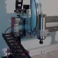
Continuing into the morning hours.. I decided to mod my voitek power supply a little. Just to clean some wiring up and add few things. Here is a sneak peak.
Dedicated 24v 31amp 750 watt Meanwell power supply and 25amp solid state relay for the Heated bed. To make sure my onyx gets to temp with the quickness.  More to come later. I'm calling it a night.
My rostock build log http://forum.seemecnc.com/viewtopic.php?f=42&t=1228
Re: Another rostock max build
So after some surgery on my voitek power supply. Here is the result. Combined that bunch of messy wires into something more manageable and got rid of lines that weren't needed.
3 dedicated 12v sources for the rambo. Plus one extra 12v source connect to fuseblock for accessories, One 5v source just in case I needed it for something, also wired to fuseblock for accessories
I will be adding a standby led light, manual power switch for the power supply, and power on Indicator on the front of the rostock.
Of course all this is just something I wanted to do and its not required.
mess of wires
after surgery
3 dedicated 12v sources for the rambo. Plus one extra 12v source connect to fuseblock for accessories, One 5v source just in case I needed it for something, also wired to fuseblock for accessories
I will be adding a standby led light, manual power switch for the power supply, and power on Indicator on the front of the rostock.
Of course all this is just something I wanted to do and its not required.
mess of wires
My rostock build log http://forum.seemecnc.com/viewtopic.php?f=42&t=1228
-
Eaglezsoar
- ULTIMATE 3D JEDI
- Posts: 7159
- Joined: Sun Apr 01, 2012 5:26 pm
Re: Another rostock max build
On the last picture you posted I see red and black wires but I see no yellow (12V) wires.
I bet you hid them so I would ask..
Carl
I bet you hid them so I would ask..
Carl
Re: Another rostock max build
Eaglezsoar wrote:On the last picture you posted I see red and black wires but I see no yellow (12V) wires.
I bet you hid them so I would ask..
Carl
if you look at the photos above the yellow wires got spliced and soldered to the red wires. here's a better picture below. All my 12v wires are 14Gauge, and 5v wires are 16 guage. That's how I determine which is which. I removed the blue -12v wire, no use for it.
Last edited by cambo3d on Fri Mar 15, 2013 5:59 pm, edited 2 times in total.
My rostock build log http://forum.seemecnc.com/viewtopic.php?f=42&t=1228
-
Eaglezsoar
- ULTIMATE 3D JEDI
- Posts: 7159
- Joined: Sun Apr 01, 2012 5:26 pm
Re: Another rostock max build
Good job, threw me a curve on that one.
Have you connected the Onyx to the 24v supply to make sure the traces can handle it without any problems?
Have you connected the Onyx to the 24v supply to make sure the traces can handle it without any problems?
Re: Another rostock max build
Haven't finished the wiring yet, but John from seemecnc says its okay and aehM_key is also using 24v for the onyx.Eaglezsoar wrote:Good job, threw me a curve on that one.
Have you connected the Onyx to the 24v supply to make sure the traces can handle it without any problems?
My rostock build log http://forum.seemecnc.com/viewtopic.php?f=42&t=1228