RAMBo to SmartController Adapter 1.0a
-
- Printmaster!
- Posts: 88
- Joined: Sun Mar 03, 2013 6:46 pm
- Location: Abilene, Texas
- Contact:
RAMBo to SmartController Adapter 1.0a
Here is a quick photo of the new RAMBo to LCD SmartController adapter (version 1.0a):
I'll have complete build instructions available later today.
By the way, I cannot get the reprap/wiki page to load (see the link on the board's silkscreen layer). That's why I am posting this thread.
Bill
The two 5 pins X 2 rows shrouded headers mount to the silkscreen side of the board (you can see their outlines on the silkscreen). All of the other connectors (the ones I have "standing on their faces") attach to the bottom of the board.I'll have complete build instructions available later today.
By the way, I cannot get the reprap/wiki page to load (see the link on the board's silkscreen layer). That's why I am posting this thread.
Bill
Last edited by Bill Havins on Mon Mar 18, 2013 11:10 am, edited 1 time in total.
"So many windmills, so little time." - Don Quixote
Re: RAMBo to SmartController Adapter 1.0a
was there a wiki for this, I coudn't get the page to come up. Maybe I was using the wrong web address?
I would think it would be under the rambolcd wiki? or maybe just haven't been updated yet.
My rostock build log http://forum.seemecnc.com/viewtopic.php?f=42&t=1228
-
- Printmaster!
- Posts: 88
- Joined: Sun Mar 03, 2013 6:46 pm
- Location: Abilene, Texas
- Contact:
Re: RAMBo to SmartController Adapter 1.0a
Here is how I constructed the board. I used a Weller WES51 soldering iron fitted with a long reach conical tip (a needle-looking tip). I set the temperature to appx. 720 degrees F. I used .022" diameter solder.
I slipped the 3 X 2 connector onto the ICSP header on the RAMBo. I then slipped the 4 X 2 connector onto the SPI header and the two 1 X 10 connectors onto the EXT-2 header. Here's a photo at this stage of construction: I then slipped the adapter PCB over the pins of the four connectors to ensure that the pins were centered: Once I was satisfied that the "fit" was good I soldered each of the pins to the PCB. Fitting and soldering these parts this way ensured that each of the connectors was precisely aligned to the headers on the RAMBo. Once I had all of the pins soldered I gently removed the pcb/connectors assembly from the RAMBo and soldered the two 5 X 2 shrouded headers to the silkscreen side of the board. I then inspected the solder joints under magnification to ensure they were all good. I then trimmed the excess from the connector pins close to the surface of the board. Here's a photo of the completed assembly as it fits over the MCU on the RAMBo board. Hope this helps!
Bill
"So many windmills, so little time." - Don Quixote
-
- Printmaster!
- Posts: 88
- Joined: Sun Mar 03, 2013 6:46 pm
- Location: Abilene, Texas
- Contact:
Re: RAMBo to SmartController Adapter 1.0a
cambo3d,cambo3d wrote:was there a wiki for this, I coudn't get the page to come up. Maybe I was using the wrong web address?
I would think it would be under the rambolcd wiki? or maybe just haven't been updated yet.
Didn't mean to step on your toes by posting this thread. I hadn't seen that you included the adapter in your build thread.
The wiki link address is printed on the silkscreen layer of the adapter PCB. But, the address does not load a page...
Bill
"So many windmills, so little time." - Don Quixote
Re: RAMBo to SmartController Adapter 1.0a
no worries, post away.
that's what the forum is for. Doesn't hurt anything to show another way of doing it.

My rostock build log http://forum.seemecnc.com/viewtopic.php?f=42&t=1228
Re: RAMBo to SmartController Adapter 1.0a
Thanks! This should help in the next few days...
The adapter came with my kit as well. I hope I won't have too much trouble soldering on the connectors...
(No trees were killed to post this message, but a large number of electrons were terribly inconvenienced.)
- Eaglezsoar
- ULTIMATE 3D JEDI
- Posts: 7159
- Joined: Sun Apr 01, 2012 5:26 pm
Re: RAMBo to SmartController Adapter 1.0a
Thanks for posting this, very informative.
Carl
Carl
Re: RAMBo to SmartController Adapter 1.0a
Where did you mount the control board? The cables seem too short
(No trees were killed to post this message, but a large number of electrons were terribly inconvenienced.)
Re: RAMBo to SmartController Adapter 1.0a
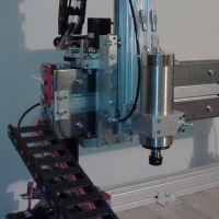
I mounted mine here, this is the only place you can mount it, and still have the lcd cables long enough to open the door.cassetti wrote:Where did you mount the control board? The cables seem too short
My rostock build log http://forum.seemecnc.com/viewtopic.php?f=42&t=1228
Re: RAMBo to SmartController Adapter 1.0a
Exactly where I ended up mounted mine. I'm in the process of final assembly, should be installing firmware tonight!
(No trees were killed to post this message, but a large number of electrons were terribly inconvenienced.)
Re: RAMBo to SmartController Adapter 1.0a
For anyone looking for the *only* post I have found that actually shows how to connect the lcd panel to the adapter. Here's the post by cambo3d (thanks dude)cassetti wrote:Where did you mount the control board? The cables seem too short
http://forum.seemecnc.com/viewtopic.php ... able#p7035
(No trees were killed to post this message, but a large number of electrons were terribly inconvenienced.)
-
- Printmaster!
- Posts: 78
- Joined: Mon Feb 18, 2013 4:08 pm
Re: RAMBo to SmartController Adapter 1.0a
Good info and kudos to both of you guys. This is very helpful info.
I will also add that the default Marlin firmware (Johnoly) github didn't work with the LCD with the download of yesterday. I was able to get Poly's to work fine first try, but had to figure out that his firmware has EEprom turned on and I had to correct max distance there rather than in the firmware upload or I crashed into the bed when printing. I will get into that later for others that may not catch that.
.
Re: RAMBo to SmartController Adapter 1.0a
thanks for that info, maybe some of us got a bad batch of lcds then??cjdavis618 wrote:Good info and kudos to both of you guys. This is very helpful info.
I will also add that the default Marlin firmware (Johnoly) github didn't work with the LCD with the download of yesterday. I was able to get Poly's to work fine first try, but had to figure out that his firmware has EEprom turned on and I had to correct max distance there rather than in the firmware upload or I crashed into the bed when printing. I will get into that later for others that may not catch that.
.
My rostock build log http://forum.seemecnc.com/viewtopic.php?f=42&t=1228
-
- Printmaster!
- Posts: 52
- Joined: Tue Feb 26, 2013 8:37 pm
Re: RAMBo to SmartController Adapter 1.0a
so i figured out why mine was showing white boxes the genes manual says to cut off the strain relief on the connectors and i did the first time and it wasnt getting pushed onto the board all the way because the wires were going into the connector too far so they couldnt be pushed onto the board all the way. I rewired all the connectors again with the strain reliefs on the crimp connectors and plugged it in and it came right up no problem. so that was my problem not sure if any other of the 3d printer noobs have this problem and think its the software! Turned out its not the software!!
-
- Printmaster!
- Posts: 88
- Joined: Sun Mar 03, 2013 6:46 pm
- Location: Abilene, Texas
- Contact:
Re: RAMBo to SmartController Adapter 1.0a
Glad you got it up and running!
"So many windmills, so little time." - Don Quixote
-
- Printmaster!
- Posts: 88
- Joined: Sun Mar 03, 2013 6:46 pm
- Location: Abilene, Texas
- Contact:
Re: RAMBo to SmartController Adapter 1.0a
There have been posts on the forum indicating that some are having troubles getting their LCDs to work when connected via the RAMBo to SmartController Adapter 1.0a. I now have mine working and it displays correctly. At his point I don't have anything plugged in to the RAMBo board other than the LCD cables and the USB cable. I have not turned on the 12 volt supply.
Finding and flashing firmware that would work was an ordeal. I am using Windows XP Pro on a Dell Workstation so some of Arduino's routines are not as elegant as they are when using a Mac. I am using Arduino 1.0.4 for Windows. I tried using Jon Oly's recent adaptation of Marlin and got nothing but the "dreaded white boxes" on the LCD. I then spent considerable time reviewing the LCD Assembly Manual and attempting to correct the Marlin code as indicated. In places the Marlin code appeared to already be "corrected," and in other places it didn't look like the examples. I chose to take a break and went for a walk.
I later chose to download Polygonhell's adaptation of Repetier and it compiled and uploaded without a hitch. The display came on, and, like any good display, demonstrated I had no thermistors attached (zeroes displayed for all temperature readings).
I come from a PIC Microcontroller background so "shuffling" may way through the Arduino IDE was a bit of a challenge. Fortunately the IDE cued me to select the 2560 board under the Tools menu. After I did that things went pretty quickly.
So, we know that at least one of the Adapters is working. I sure hope all of the others come on line soon! (I do need to go back into the firmware and turn off EEPROM references, etc. But, at least I got it to this point.)
Cheers!
Bill
Last edited by Bill Havins on Sun Mar 24, 2013 7:56 pm, edited 1 time in total.
"So many windmills, so little time." - Don Quixote
Re: RAMBo to SmartController Adapter 1.0a
glad you got it to work, maybe im the only one with bad lcd, even using repetier firmware, i can't get it to display correctly
My rostock build log http://forum.seemecnc.com/viewtopic.php?f=42&t=1228
- gsnover
- Prints-a-lot
- Posts: 28
- Joined: Sat Mar 16, 2013 2:31 pm
- Location: Bennington VT | Montreal, QC
- Contact:
Re: RAMBo to SmartController Adapter 1.0a
Hey guys, thanks for this thread. I am a MAX noob, just finished the build. PolygonHell's Repetier firmware works for my LCD, but can I ask about the changes everyone has mentioned they will make to that firmware.cjdavis618 wrote:Good info and kudos to both of you guys. This is very helpful info.
I will also add that the default Marlin firmware (Johnoly) github didn't work with the LCD with the download of yesterday. I was able to get Poly's to work fine first try, but had to figure out that his firmware has EEprom turned on and I had to correct max distance there rather than in the firmware upload or I crashed into the bed when printing. I will get into that later for others that may not catch that.
.
1) What is EEprom and why do you want to turn it off?
2) mhackney mentioned making changes to use 1/16 microstepping, how is that done?
help me understand! Much appreciated.
-Guy
Rostock Max - Shakira "her hips don't lie"
Rambo 1.1 | Onyx | LCD | Marlin-for-Rostockmax-RamboLCD
KISSlicer
Rambo 1.1 | Onyx | LCD | Marlin-for-Rostockmax-RamboLCD
KISSlicer
-
- Printmaster!
- Posts: 88
- Joined: Sun Mar 03, 2013 6:46 pm
- Location: Abilene, Texas
- Contact:
Re: RAMBo to SmartController Adapter 1.0a
Guy,gsnover wrote: Hey guys, thanks for this thread. I am a MAX noob, just finished the build. PolygonHell's Repetier firmware works for my LCD, but can I ask about the changes everyone has mentioned they will make to that firmware.
1) What is EEprom and why do you want to turn it off?
2) mhackney mentioned making changes to use 1/16 microstepping, how is that done?
help me understand! Much appreciated.
-Guy
It might be better for you to start another thread so others will see you need questions answered. The title of the thread you start might be something like, "How Do I Change Printer Configuration Settings In Arduino IDE?"
If you are familiar with programming and programming microcontrollers the short version of the answer you need is, "Download The Arduino IDE, Download Polygonhell's Repetier firmware revision, open the Configuration.h file in Polygonhell's firmware revision, find the lines of code that need to be changed and make the changes, save the changes, then compile and upload the firmware to your RAMBo."
If you are not familiar with programming and programming microcontrollers I don't mean to put you off. Yours is a very important question that really should be addressed in some detail for new users to read and study. Once you know the routine it will be less intimidating. But the question might best be answered with a "step-by-step" procedure that walks you through the process. That might be better addressed in a separate thread.
Good luck!
Bill
"So many windmills, so little time." - Don Quixote
- gsnover
- Prints-a-lot
- Posts: 28
- Joined: Sat Mar 16, 2013 2:31 pm
- Location: Bennington VT | Montreal, QC
- Contact:
Re: RAMBo to SmartController Adapter 1.0a
I think I found my answers, unless someone suggests otherwise.
1) I will keep EEPROM enabled and make changes from the EEPROM menu in Repetier. 2) Such as changing the steps per mm for 16 micro stepping as mhackney described in another post.
Do I also need to change the configuration file lines such as? :
#define MICRO_STEPS 8
#define MICROSTEP_MODES {8,8,8,8,8} // [1,2,4,8,16]
I assuming that the eeprom values for steps per mm override the these, but if someone can confirm this I will sleep better.
Rostock Max - Shakira "her hips don't lie"
Rambo 1.1 | Onyx | LCD | Marlin-for-Rostockmax-RamboLCD
KISSlicer
Rambo 1.1 | Onyx | LCD | Marlin-for-Rostockmax-RamboLCD
KISSlicer
Re: RAMBo to SmartController Adapter 1.0a
@gsnover - in answer to your last question correct, don't edit microsteps in configuration.h - changes to that file only work if you have disabled eeprom. Enabling eeprom overwrites that data. You will need to update all 4 steps per mm settings in the eeprom.
Guys, I have the LCD adapter finally up and running, but it only turns on when the USB is plugged in! How do make it stay on all the time?
Do I need to remove the jumper on the "PSEL USB" on the RAMBo? Or is there a setting in the firmware/eeprom that enables this?
Guys, I have the LCD adapter finally up and running, but it only turns on when the USB is plugged in! How do make it stay on all the time?
Do I need to remove the jumper on the "PSEL USB" on the RAMBo? Or is there a setting in the firmware/eeprom that enables this?
(No trees were killed to post this message, but a large number of electrons were terribly inconvenienced.)
Re: RAMBo to SmartController Adapter 1.0a
move the jumper to 12v power supply
My rostock build log http://forum.seemecnc.com/viewtopic.php?f=42&t=1228
- Eaglezsoar
- ULTIMATE 3D JEDI
- Posts: 7159
- Joined: Sun Apr 01, 2012 5:26 pm
Re: RAMBo to SmartController Adapter 1.0a
You need to move the jumper. Posted by johnoly99:
Re: LCD Smart Adapter
Postby johnoly99 » Tue Jan 29, 2013 8:01 pm
zmocar, there is a jumper on the rambo board, next to the USB plug, it's a 3-pin jumper. In one position, your board gets power from the USB cable, and in the other, the board gets power from your power supply. Move the jumper to the other position to power the board without USB cable attached, sorry, I'll add that to the wiki right now
Re: RAMBo to SmartController Adapter 1.0a
yup, I suspected that was the case. Thanks!
(No trees were killed to post this message, but a large number of electrons were terribly inconvenienced.)