Has anyone wondered or knows what the slots and holes are for on the top plate of the rostock max?
or maybe no reason at all for them being there?
Another rostock max build
Re: Another rostock max build
My rostock build log http://forum.seemecnc.com/viewtopic.php?f=42&t=1228
-
Eaglezsoar

- ULTIMATE 3D JEDI
- Posts: 7159
- Joined: Sun Apr 01, 2012 5:26 pm
Re: Another rostock max build
Best guess is they wanted to make sure it was ventilated and went a little overboard.
Re: Another rostock max build
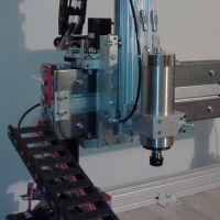
Maybe for this: http://www.youtube.com/watch?v=j8B1PypVCvU&hd=1 ...and other future extensions 
Re: Another rostock max build
yeah i saw that before, but i thought maybe there was a reason for this version.aehM_Key wrote:Maybe for this: http://www.youtube.com/watch?v=j8B1PypVCvU&hd=1 ...and other future extensions
My rostock build log http://forum.seemecnc.com/viewtopic.php?f=42&t=1228
Re: Another rostock max build
starting to get my heatbed prepped for wiring and I did not realize now small the thermistor really is. This is a delicate operation and now can I see why this could short out the rambo ports. Especially if your not careful.
Last edited by cambo3d on Sat Mar 16, 2013 5:08 pm, edited 1 time in total.
My rostock build log http://forum.seemecnc.com/viewtopic.php?f=42&t=1228
Re: Another rostock max build
Here are some close up shots.
I put some thermal heatsink compound to fill in the air gaps. Double checked with a meter to make sure nothing was shorting. I will rtv it to seal it in place.
My rostock build log http://forum.seemecnc.com/viewtopic.php?f=42&t=1228
-
Eaglezsoar
- ULTIMATE 3D JEDI
- Posts: 7159
- Joined: Sun Apr 01, 2012 5:26 pm
Re: Another rostock max build
May I ask what type of camera you use to take those amazing closeups?
Re: Another rostock max build
Casio EX-Z1050
(The pictures are ok, but there is much more possible, e.g. http://www.abload.de/img/new-out999993n7t.jpg )
(The pictures are ok, but there is much more possible, e.g. http://www.abload.de/img/new-out999993n7t.jpg
Re: Another rostock max build
Actually the close ups were taken by a microscope camera. Comes in handy when your troubleshooting circuit boards too.Eaglezsoar wrote:May I ask what type of camera you use to take those amazing closeups?
I bought a cheap chinese made one off of ebay, seems to work descent and gets the job done.
Last edited by cambo3d on Sat Mar 16, 2013 5:17 pm, edited 2 times in total.
My rostock build log http://forum.seemecnc.com/viewtopic.php?f=42&t=1228
-
Eaglezsoar
- ULTIMATE 3D JEDI
- Posts: 7159
- Joined: Sun Apr 01, 2012 5:26 pm
Re: Another rostock max build
Amazing!
Re: Another rostock max build
(Sorry, I thought you where talking about the other ones. The camera is written in the Exif data.)
Re: Another rostock max build
Most of my photos were taken with the casio but not the close ups.aehM_Key wrote:(Sorry, I thought you where talking about the other ones. The camera is written in the Exif data.)
My rostock build log http://forum.seemecnc.com/viewtopic.php?f=42&t=1228
Re: Another rostock max build
Heat spreader (http://www.3dfabricationworks.com/rosto ... rades.html) mounted on top of the Onyx heat bed. In between the heat spreader and the onyx I laid a layer of thermal heatsink compound to help with heat transfer. edit: I had problems with the aluminum bowing, so it was removed later on.
Soldered everything underneath. 10awg Flexible silicone wire is no problem for tight spaces and its rated for 200 degrees Celsius. I should also mention that I used a 230/150 watt soldering iron to attach the larger 10 gauge wires to the heat bed.
Fit perfectly through the existing hole, no need to widen.
Solid state relay mounted behind my electronics door, wiring almost complete.
Last edited by cambo3d on Wed Apr 03, 2013 12:06 am, edited 1 time in total.
My rostock build log http://forum.seemecnc.com/viewtopic.php?f=42&t=1228
-
foshon

- Printmaster!
- Posts: 600
- Joined: Fri Mar 08, 2013 3:05 pm
- Location: Just to the right of SeeMeCNC
Re: Another rostock max build
cambo3d wrote:Continuing into the morning hours.. I decided to mod my voitek power supply a little. Just to clean some wiring up and add few things. Here is a sneak peak. Dedicated 24v 31amp 750 watt Meanwell power supply and 25amp solid state relay for the Heated bed. To make sure my onyx gets to temp with the quickness.More to come later. I'm calling it a night.
Why not just use the 24v PS to power the RAMbo? It's rated for up to 36v. I have a MendelMax running on a 24v PS to power the linear y-axis upgrade kapton heater. It doesn't complain at all.
Purple = sarcasm
Please do a board search before posting your question, many have been answered with very time consuming detail already.
Please do a board search before posting your question, many have been answered with very time consuming detail already.
Re: Another rostock max build
Why not just use the 24v PS to power the RAMbo? It's rated for up to 36v. I have a MendelMax running on a 24v PS to power the linear y-axis upgrade kapton heater. It doesn't complain at all.[/quote]
The steppers that I have aren't rated for 24v and I wanted a dedicated supply for the heat bed.
The steppers that I have aren't rated for 24v and I wanted a dedicated supply for the heat bed.
My rostock build log http://forum.seemecnc.com/viewtopic.php?f=42&t=1228
-
MorbidSlowBurn

- Printmaster!
- Posts: 169
- Joined: Sun Mar 03, 2013 5:33 pm
Re: Another rostock max build
I believe was foshon is mentioning is that each power input has its own bus on the PCB. I can't confirm it because the wiki is down (http://reprap.org/wiki/Rambo). But if someone else more familiar with the board could confirm this it would be appreciated. Basically what the seperate bus means is that you can have 12V driving you steppers and 24V driving your heated bed with no conflict on the board. Just make sure you wire it up right..
Re: Another rostock max build
on rail is for the hotend(s) and fan(s)
and the 3rd rail is for the electronics itself (could also be powered via USB, depends on the jumper) and the steppers.
Re: Another rostock max build
I have already researched all this. while you could run everything separately, my rambo is powered by the 12v pc supply for a reason.MorbidSlowBurn wrote:I believe was foshon is mentioning is that each power input has its own bus on the PCB. I can't confirm it because the wiki is down (http://reprap.org/wiki/Rambo). But if someone else more familiar with the board could confirm this it would be appreciated. Basically what the seperate bus means is that you can have 12V driving you steppers and 24V driving your heated bed with no conflict on the board. Just make sure you wire it up right..
The reason why I didn't run the 24v through the rambo is because of its 15amp current limitation for the heat bed and possibly the connectors that it uses. . The onyx will draw around 20 amps at 24v. The other rails are rated at 5amps. If you used a 12v supply for the heat bed this would be okay because at 12v the onyx draws only 10amps.
so before you start thinking you can just throw anything in there. There are other factors to consider.
Last edited by cambo3d on Tue Mar 19, 2013 12:34 pm, edited 2 times in total.
My rostock build log http://forum.seemecnc.com/viewtopic.php?f=42&t=1228
Re: Another rostock max build
Will you change the firmware from PID-PWM to maybe a bang-bang controller for the heatbed, or how will it work with the relay?
Re: Another rostock max build
The heat bed output on the rambo will be used as the input to activate the SSR. I will be trying the default configuration first. I will see what works best but PID is what I was aiming for. Solid state relays are used quite often for heater circuits with pid controller.aehM_Key wrote:Will you change the firmware from PID-PWM to maybe a bang-bang controller for the heatbed, or how will it work with the relay?
My rostock build log http://forum.seemecnc.com/viewtopic.php?f=42&t=1228
Re: Another rostock max build
Sorry, I should have looked up earlier that a solid state relay isn't a relay
English is not my first language and especially all these special technical terms are sometimes problematic
English is not my first language and especially all these special technical terms are sometimes problematic
-
foshon
- Printmaster!
- Posts: 600
- Joined: Fri Mar 08, 2013 3:05 pm
- Location: Just to the right of SeeMeCNC
Re: Another rostock max build
That's interesting. My RAMPS 1.4 runs on a single 24v supply. I was under the impression that the RAMbo was a one board replacement. Forgive my intrusion.cambo3d wrote:I have already researched all this. while you could run everything separately, my rambo is powered by the 12v pc supply for a reason.MorbidSlowBurn wrote:I believe was foshon is mentioning is that each power input has its own bus on the PCB. I can't confirm it because the wiki is down (http://reprap.org/wiki/Rambo). But if someone else more familiar with the board could confirm this it would be appreciated. Basically what the seperate bus means is that you can have 12V driving you steppers and 24V driving your heated bed with no conflict on the board. Just make sure you wire it up right..
The reason why I didn't run the 24v through the rambo is because of its 15amp current limitation for the heat bed and possibly the connectors that it uses. Also as stated before my steppers aren't rated for 24v.. The onyx will draw around 20 amps at 24v. The other rails are rated at 5amps. If you used a 12v supply for the heat bed this would be okay because at 12v the onyx draws only 10amps.
so before you start thinking you can just throw anything in there. There are other factors to consider.
Purple = sarcasm
Please do a board search before posting your question, many have been answered with very time consuming detail already.
Please do a board search before posting your question, many have been answered with very time consuming detail already.
Re: Another rostock max build
it is provided you keep everything within specs.
My rostock build log http://forum.seemecnc.com/viewtopic.php?f=42&t=1228
Re: Another rostock max build
more progress, ran the wires for the end stop switches, mounted the accessory fuse block.
My rostock build log http://forum.seemecnc.com/viewtopic.php?f=42&t=1228
Re: Another rostock max build
Today I decided to tackle an issue that I put off since i started working on the wiring.
After installing the build surface. It was not flat and seemed to have a bow in the middle. The aluminum that I was using as a heat spreader wasn't completely flat to begin with but I should have been able to flatten it out somewhat once I tightened the screws down but it actually got worse. I took everything off to check tolerances of the spacers they were all between 3.99mm and 3.97mm, I had two that measured over 4mm. To my surprise star spacer was also fairly flat.
This leads me to believe that the actual mounting surface of the rostock was the culprit and I need to solve this. I suspect its lies in how tight I have the frame assembled and the tolerances of laser cut parts.
I've been thinking of implementing some sort of bed leveling device to account for some of the inconsistency of the rostock frame.
My rostock build log http://forum.seemecnc.com/viewtopic.php?f=42&t=1228