
Each hot end will "do its own thing" so if they ooze with 1 they will ooze with 2! How to use the dual extruders in software is where the rubber meets the road. Here are some of the options:
1) simply use the 2nd extruder for support material. KISS, Slic3r and other slicers have support for dual extruders to generate gcode for support material (wow, say that 10 times fast!)
2) print in 2 colors. There are several variants for this:
2a) on a layer-by-layer basis. I am not aware of any slicers that do this but I have a friend who is generating a post processor that will allow inserting extruder selection for a range of layers. So you could do top/bottom shell in one color and in between in another, stripes, etc. Lots of creative opportunity here.
2b) on an object by object basis. Here, a final object is broken down into several sub components. Each of these is then assigned to a specific extruder (color) and merged for printing. This is the approach RepRapPro (Adrian Bowyer's company) took with their recently introduced tricolor Mendel. They have a special slicer (in beta) RepRapPro Slicer that does the magic of combining several objects into 1. This is still a pretty complicated process and not very intuitive.
These are the only options I am aware of for multiple extrusion printing at this time.
[I am not worthy of being mentioned in the same post as Hoss!]
cheers,
Michael
Mhackney's Rostock Max
Re: Mhackney's Rostock Max
Sublime Layers - my blog on Musings and Experiments in 3D Printing Technology and Art
Start Here:
A Strategy for Successful (and Great) Prints
Strategies for Resolving Print Artifacts
The Eclectic Angler
Re: Mhackney's Rostock Max
@MorbidSLowBurn - we cross posted! Although, I didn't say what my plans are! I am actually more interested in multiple colors than using it for support - although I am sure I'll do that too.
Sublime Layers - my blog on Musings and Experiments in 3D Printing Technology and Art
Start Here:
A Strategy for Successful (and Great) Prints
Strategies for Resolving Print Artifacts
The Eclectic Angler
Re: Mhackney's Rostock Max
I think one of the most useful features would be, to print with different nozzle sizes. Very fine for the perimeters and thick for the infill. This would look great and be fast..maybe 
Re: Mhackney's Rostock Max
That would be a useful feature. KISS has a feature - Stacked Layers that helps a bit to speed up infills.
Sublime Layers - my blog on Musings and Experiments in 3D Printing Technology and Art
Start Here:
A Strategy for Successful (and Great) Prints
Strategies for Resolving Print Artifacts
The Eclectic Angler
-
Polygonhell
- ULTIMATE 3D JEDI
- Posts: 2417
- Joined: Mon Mar 26, 2012 1:44 pm
- Location: Redmond WA
Re: Mhackney's Rostock Max
I've given the dual extruder thing some thought and I think something similar to mill auto tool changers is a good way to go, the idea being to park the unused tool bed preferably with something that stops the nozzle leaking plastic.
That way you don't have two nozzles draggin over the print, you could you the standard tool offsets mechanism to deal with slightly different mounting points of the tools.
It's a little tricky todo on a standard mendel design because of the limited Z speed, but on a delta printer it seems like a potentially interesting solution, I actually sketched a couple of designs for this, one using a spring loaded tool holder, and the other neodymium magnets.
I'm mostly interested in support, but also in using paste extruders (for UV sensitive resins) in combination with the standard hotend.
Printer blog http://3dprinterhell.blogspot.com/
-
MorbidSlowBurn

- Printmaster!
- Posts: 169
- Joined: Sun Mar 03, 2013 5:33 pm
Re: Mhackney's Rostock Max
@mhackney- you read my mind. I am hoping to do dual colors eventually myself. And with the every other layer color I thought I saw a tab in Kisslicer that allows code to be placed at each layer. I am not familiar enough with g-code to know if this would work to keep swapping heads.
@polygonhell- I have been thinking about the tool changer design also. I don't have direct experiecne with them. But it sounds like it would be a great solution minimizing head contact possibilities.
@polygonhell- I have been thinking about the tool changer design also. I don't have direct experiecne with them. But it sounds like it would be a great solution minimizing head contact possibilities.
Re: Mhackney's Rostock Max
Polygonhell hit it. Spring loaded tool that uses magnets to retract the hotend. Or bring it down. Magnet on raise or lower, spring would counteract the other. Hell could even rig up a little door to cover the nozzle to keep it from leaking and pull to the side when lowered. Simply electro magnet and a relay could be controlled by the rambo. Light enough spring would make for a small magnet? Maybe...... could work. I don't have the time to work on anything so we are all interested to see the development and eventually the sale of a dual setup. Goodluck boys.
Re: Mhackney's Rostock Max
Hi mhackney,
I think you said you're not using any retraction anymore (?), because of the wipe-feature of Kisslicer. Can you upload your current settings? I think here: http://forum.seemecnc.com/viewtopic.php ... icer#p6164 you have 3mm retraction.
I think you said you're not using any retraction anymore (?), because of the wipe-feature of Kisslicer. Can you upload your current settings? I think here: http://forum.seemecnc.com/viewtopic.php ... icer#p6164 you have 3mm retraction.
Re: Mhackney's Rostock Max
I'm still using 3mm retraction along with 3mm of swipe. I have not completely dialed in the Max yet. It is great about 90% of the time though. Settings are the same as I posted except for experimental tweaks and adding several different ABS materials to the config.
Sublime Layers - my blog on Musings and Experiments in 3D Printing Technology and Art
Start Here:
A Strategy for Successful (and Great) Prints
Strategies for Resolving Print Artifacts
The Eclectic Angler
Add-A-Struder update
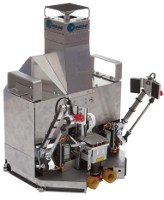
Completing the Add-S-Struder kit and putting on the Max. I went ahead and installed Av8r RC's great mod to widen the spool arm and a nice round spool axel. Having now printed both the flat plate spacers and the 8 small standoff spacers, I highly recommend using the the standoffs! They are really quick to print and look great. Here's the arm sitting on the Max:
[img]http://mhackney.zenfolio.com/img/s4/v64 ... 7790-3.jpg[/img]
I am going to relocated my RAMBo to an interior partition wall and move the LCD between the X and Y towers so the extruder arm won't interfere with anything.
I've also completed assembly of the Steve's Extruder. This is the forth one I've built so I am getting pretty good at it! Before I install it, I have a few mods to do - more on that later.
Sublime Layers - my blog on Musings and Experiments in 3D Printing Technology and Art
Start Here:
A Strategy for Successful (and Great) Prints
Strategies for Resolving Print Artifacts
The Eclectic Angler
-
Eaglezsoar

- ULTIMATE 3D JEDI
- Posts: 7159
- Joined: Sun Apr 01, 2012 5:26 pm
Re: Extruder Guide Insert
Are these available yet, I didn't see them but I am half blind and idiotic so take that into account.mhackney wrote:I posted the CAD for my idea to prevent "filament ejection" from the Steve's extruder yesterday. Today I machined the parts and put it back together. Here's what it looks like:
Machined Bowden adapter and Delrin insert:
[img]http://mhackney.zenfolio.com/img/s2/v70 ... 4322-3.jpg[/img]
Assembled:
[img]http://mhackney.zenfolio.com/img/s8/v75 ... 4262-3.jpg[/img]
The Delrin is a nice friction fit in the adapter and is about 5/8" long overall. I installed it and pulled up a part that always gives me trouble to print. All I can say is - "Wow, I immediately noticed a difference!" Firstly, retracts actually sound different. And they are obviously much "crisper". I didn't have any issues with the filament jamming and I've always had to abort printing this object with these settings. I am printing one of the cool single piece bearings now to show off photos.
I have designed a new replacement adapter that mounts in from the top so it is much easier to install, remove any damaged filament, start new filament, etc. It will have this guide insert integrated. I plan to offer these on my site in a week or so. But whatever you do, some sort of a guide like Polygonhell's or this one is a required upgrade to Steve's extruder.
Re: Mhackney's Rostock Max
Not yet - I am actually working on a solid acetal version that mounts in from the top. While this design works spectacularly well, it is a pain to change filament and to assemble this into the extruder because the insert interferes with the rollers because of the way the extruder slides together. I am working on a top attachment that will make if very easy to remove the bowden from the extruder, change filament, etc. Was just in the shop making a refinement to try out. Stay tuned!
Sublime Layers - my blog on Musings and Experiments in 3D Printing Technology and Art
Start Here:
A Strategy for Successful (and Great) Prints
Strategies for Resolving Print Artifacts
The Eclectic Angler
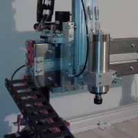
2nd hot end assembled
Ok, got the 2nd hot end put together. This is the 5th SeeMeCNC hot end I've assembled.
[img]http://mhackney.zenfolio.com/img/s11/v3 ... 3604-3.jpg[/img]
I'll let the Permatex Copper cure overnight. I put a little dab of Omega Therm 201 thermal paste on the very tip of the thermistor to get good contact with the hot end.
I have a little wiring to do and some work on the hotend holder. The Add-A-Struder kit does not come with a new hot end holder. The original holder shipped with the Max has spots for 3 hot ends but 1) it is VERY tight and 2) the hot end interferes with the lower delta platform. I am prototyping a quick change tool holder and will make a new 2 hot end holder to go with it. The folks over at Laser Accents sent me their cool double hot end mounting plate. It comes with 3 melamine short (3/8") standoffs that could be used to lower the mount so the hot ends extend out the bottom enough to clear the delta platform. This would be a good solution for a "near stock" setup but I have something a little different in mind. I want a quick change tool holder so I can experiment with:
dual and triple hot ends
my JHead hot end
my Micro Extruder (no Bowden tube)
a pen holder
a diamond drag engraver
a dial indicator holder
The idea is that each of these tools will be mounted to a holder that can be easily installed/removed from the delta platform.
Sublime Layers - my blog on Musings and Experiments in 3D Printing Technology and Art
Start Here:
A Strategy for Successful (and Great) Prints
Strategies for Resolving Print Artifacts
The Eclectic Angler
Re: Mhackney's Rostock Max
So what's the idea? Put in new tool and set the z and go? Just like a vmc?
Re: Mhackney's Rostock Max
Basically, yes. WIth the EEPROM settings, its easy to set the Z to a new value.
Sublime Layers - my blog on Musings and Experiments in 3D Printing Technology and Art
Start Here:
A Strategy for Successful (and Great) Prints
Strategies for Resolving Print Artifacts
The Eclectic Angler
Re: Mhackney's Rostock Max
Is there anyway to set a fixture offset? Maybe put a laser instead of hotend to engrave.
Re: Mhackney's Rostock Max
Mhackney,
Have you ever tested how flat your bed is with a indicator? I just got your alum plate so I had to take everything apart to put it on. I noticed that when I put the glass back on the bed the middle of the bed was really high(not heated), so I decided to put a indicator in the platform. Set a zero in the middle of the bed and swept in x and y. I seem you be .020 to .034 from center to the outside depending on the direction. Which is no fault of your plate. I am not saying that. Looks like the snowflake is warped among other things. Almost looks to have brown heat marks on it and seems as if it starting to delaminate in some places. I run the be around 80 checked with a thermocouple.
I have not measured the spacers and I should have ran the indicator along the top of machine without the bed to see what it shows. Makes setting Z0 in 3 spots a little tuff. Just wondering who else has this problem. I'm gonna have to fix that.
By the way thanks for posting about the abs glue. Works to good.
Re: Mhackney's Rostock Max
In order to measure the flatness of the build surface on the machine you need to make sure your delta carriage is calibrated first - a bit of a chicken and egg problem. I've got mine dialed in and now when I measure with an indicator it is flat to within a couple of tho inches.
My snowflake didn't appear to be warped or have heat marks on it but I mostly ran at 70°C. I've been running at 80°C lately so maybe I'll see that.
My snowflake didn't appear to be warped or have heat marks on it but I mostly ran at 70°C. I've been running at 80°C lately so maybe I'll see that.
Sublime Layers - my blog on Musings and Experiments in 3D Printing Technology and Art
Start Here:
A Strategy for Successful (and Great) Prints
Strategies for Resolving Print Artifacts
The Eclectic Angler
Re: Mhackney's Rostock Max
fyi the aluminum plate that I got wasn't flat either and once I put it on the machine I was hoping tightening the screws down would even it out but it didn't. Made it worse.
So will have to go back and double check the flatness of the rostock frame itself and other components and shim where necessary.
So will have to go back and double check the flatness of the rostock frame itself and other components and shim where necessary.
My rostock build log http://forum.seemecnc.com/viewtopic.php?f=42&t=1228
Re: Mhackney's Rostock Max
I had similar problems, both before and after I added an alum spreader (made it myself).
What I did to solve my problem was. Remove the glass plate. Loosen the hotbed screws about half a turn. Get the hotbed as hot as it will go (mine only gets up to about 85). And then snug up the screws in a star pattern, and go back and tighten all of them in a star pattern. It is extremely critical that you tighten each one up with the same amount of force. If you tighten one up more than the rest your going to have a low spot. Let the hotbed cool back down and put your glass back on.
It's probably more important to tighten all the screws evenly than it is to do it while its hot. But doing it while it's hot will help with any thermal expansion you may get with the hotbed.
Re: Mhackney's Rostock Max
Thanks Av8r RC, I didn't mention tightening in a star pattern in the instructions but it turns out that is how I mount my plate too (and I have taken it on and off quite a few times). I do it cold and have not observed a flatness issue.
Sublime Layers - my blog on Musings and Experiments in 3D Printing Technology and Art
Start Here:
A Strategy for Successful (and Great) Prints
Strategies for Resolving Print Artifacts
The Eclectic Angler
-
Eaglezsoar
- ULTIMATE 3D JEDI
- Posts: 7159
- Joined: Sun Apr 01, 2012 5:26 pm
Re: Mhackney's Rostock Max
That's a great tip! Harbor Freight had a small 1/4" drive torque wrench that you could insert a bit into, that would help to make sure that they are torqued the same.Av8r RC wrote:I had similar problems, both before and after I added an alum spreader (made it myself).
What I did to solve my problem was. Remove the glass plate. Loosen the hotbed screws about half a turn. Get the hotbed as hot as it will go (mine only gets up to about 85). And then snug up the screws in a star pattern, and go back and tighten all of them in a star pattern. It is extremely critical that you tighten each one up with the same amount of force. If you tighten one up more than the rest your going to have a low spot. Let the hotbed cool back down and put your glass back on.
It's probably more important to tighten all the screws evenly than it is to do it while its hot. But doing it while it's hot will help with any thermal expansion you may get with the hotbed.
A cautionary tale - don't always trust those STLs!
I wanted to print a black penguin for my nephew's 11th birthday tomorrow. Not too many options on Thingiverse so I picked Tux Linux Penguin. Started to print and my first layer just was not sticking. I noticed that the gap between the nozzle and bed was too big, so I went into EEPROM settings and increased the max lengths by .5mm and tried again. No luck so I increased to 1mm linger thinking that something had changed. Still no luck. While I was waiting for the print to start I started rotating the STL in KISS and realized the model sits above the build surface! So don't always trust those STLs.
Sublime Layers - my blog on Musings and Experiments in 3D Printing Technology and Art
Start Here:
A Strategy for Successful (and Great) Prints
Strategies for Resolving Print Artifacts
The Eclectic Angler
24 V Power Supply and Heated Bed Musings
I posted this yesterday in another thread but wanted to capture this in my build thread:
Basically in a resistive heating element like that in an Onyx, power is converted to heat. Increasing power will get the temperature to a set value faster - as long as the device can handle it. So, using a bit of electronics calculations, you need to figure out how to apply more power to the Onyx (again, as long as you don't over power it and melt the traces, etc). The equations used are Ohm's Law and the power law:
Ohm's Law is V = I*R where V = voltage, I = current and R = resistance. The Onyx's resistance is fixed at 1.3Ω. Rearranging the formula, R = V/I or 1.3Ω = V/I. This tells you that current will be proportional to voltage. So, if your power supply can supply the current, increasing voltage from 12 to 15 to 24 volts will be met with a proportional increase in current. With this knowledge, you can then apply the power law: P = I*V where P is power. So, having calculated V and I with Ohm's law, you can calculate the power by plugging those into the power law, or you could use an online calculator that calculates power for you using these equations. With this calculator, enter the Onyx's resistance and the voltage and it will calculate the current and power. Try it for 12, 15 and 24 volts and you will see that power increases (as does amperage).
12V - 9.2A - 111W
15V - 11.5A - 173W
24V - 18.5A - 443W
The question has been asked, is the Onyx engineered to handle 17A of current? And, of course, the RAMBo version 1.1 is limited to 15A 12-24V so you won't be able to pump more than 15A to the Onyx. Plug 15A into the equation with the resistance and you get 19.5V and 292.5W. I've talked to Steve at SeeMeCNC and he thinks the board was designed for 12A or so with a few amps margin of error. He believed it should handle 15A but told me to try at my own risk. I have been running my Rostock on a 24V 14.6A (350W) supply for a few weeks now. I have over 30 hours of "heat time" on the Onyx - admittedly not a lot of time but folks here seem impatient and thirsty for information so I'll tell you what I've learned!
I see no evidence of fatigue, blistering, excessive warpage or any other physical damage to either side of the Onyx or the electronics connector pad. The LED works properly too - I am running the 24V through the RAMBo to power everything.
SIDEBAR: I saw an earlier post somewhere about running steppers at 24V. There is absolutely no problem with doing this. Read section 7 of this great overview on steppers and this article on Stepper Motor Voltages Explained. The SeeMeStepper is this one 42BYGHW811 and the rated voltage spec is 3.1V. So, running at 24V is only 8X, which from the Gecko article:
With my 24V supply, the naked Onyx heats incredibly fast to 100°C. Putting anything on it like aluminum or glass or both adds thermal mass that needs to be heated via convection. This takes power, so of course it takes longer to get to temperature with either or both of these for the same power input. Currently, I have my 1/8" thick aluminum heat dissipator and the borosilicate glass plate on top of that - a fair amount of extra mass to heat up. Below is my temperature-time curve from Repetier that shows heating the Onyx from 21°C to 80°C with the aluminum and glass in place. It took just a hair over 5 minutes. I've done the auto PID calibrate on this and you can see the temperature rises and stabilizes pretty quickly. The temperature - measured with a thermocouple - at the center of glass surface after stabilizing was 80.1°C and several points at the very edge of the glass were 79.2° and higher - very even temperature distribution.
I have also done some quick heat up tests with just the aluminum and just the glass plate. The time decreases by about 1/2 in both cases - the aluminum is a little quicker to heat than just glass.
Only time will tell if there is any damage to the Onyx. I am not running mine at greater than 80°C so I can't say what would happen increasing power to get up to say 100°C for an extended time. I'm quite happy with the performance of both the heated bed and the rest of the system. I have added a 24 to 12 volt convertor to run my auxiliary fans and LEDs. The fan controlled via software runs fast at 100% so I just turn it down to 50% or so.
Finally, the last thing I'll add is, I have purchased one of the 24V silicone heat pads. I intend to test it as soon as I have time. It has a built in thermistor too. The challenge with it is it is not perfectly flat. There is a bulge where the wires come in that has to be accounted for. I haven't decided how I want to address that yet. I will likely attach it to the bottom side of one of my aluminum plates with Permatex Copper around the edges to get good physical contact and then elevate the assembly with standoffs but without the snowflake spacer included in the Rostock kit.
Shewwww, sorry for the long winded post!
Basically in a resistive heating element like that in an Onyx, power is converted to heat. Increasing power will get the temperature to a set value faster - as long as the device can handle it. So, using a bit of electronics calculations, you need to figure out how to apply more power to the Onyx (again, as long as you don't over power it and melt the traces, etc). The equations used are Ohm's Law and the power law:
Ohm's Law is V = I*R where V = voltage, I = current and R = resistance. The Onyx's resistance is fixed at 1.3Ω. Rearranging the formula, R = V/I or 1.3Ω = V/I. This tells you that current will be proportional to voltage. So, if your power supply can supply the current, increasing voltage from 12 to 15 to 24 volts will be met with a proportional increase in current. With this knowledge, you can then apply the power law: P = I*V where P is power. So, having calculated V and I with Ohm's law, you can calculate the power by plugging those into the power law, or you could use an online calculator that calculates power for you using these equations. With this calculator, enter the Onyx's resistance and the voltage and it will calculate the current and power. Try it for 12, 15 and 24 volts and you will see that power increases (as does amperage).
12V - 9.2A - 111W
15V - 11.5A - 173W
24V - 18.5A - 443W
The question has been asked, is the Onyx engineered to handle 17A of current? And, of course, the RAMBo version 1.1 is limited to 15A 12-24V so you won't be able to pump more than 15A to the Onyx. Plug 15A into the equation with the resistance and you get 19.5V and 292.5W. I've talked to Steve at SeeMeCNC and he thinks the board was designed for 12A or so with a few amps margin of error. He believed it should handle 15A but told me to try at my own risk. I have been running my Rostock on a 24V 14.6A (350W) supply for a few weeks now. I have over 30 hours of "heat time" on the Onyx - admittedly not a lot of time but folks here seem impatient and thirsty for information so I'll tell you what I've learned!
I see no evidence of fatigue, blistering, excessive warpage or any other physical damage to either side of the Onyx or the electronics connector pad. The LED works properly too - I am running the 24V through the RAMBo to power everything.
SIDEBAR: I saw an earlier post somewhere about running steppers at 24V. There is absolutely no problem with doing this. Read section 7 of this great overview on steppers and this article on Stepper Motor Voltages Explained. The SeeMeStepper is this one 42BYGHW811 and the rated voltage spec is 3.1V. So, running at 24V is only 8X, which from the Gecko article:
makes it still well within spec. I can not tell any difference in my steppers running at 24V, they don't seem to run any hotter - basically, everything works just fine and heating is much faster.An empirically derived maximum is 25:1, meaning the power supply voltage should never exceed 25 times the motor’s rated voltage
With my 24V supply, the naked Onyx heats incredibly fast to 100°C. Putting anything on it like aluminum or glass or both adds thermal mass that needs to be heated via convection. This takes power, so of course it takes longer to get to temperature with either or both of these for the same power input. Currently, I have my 1/8" thick aluminum heat dissipator and the borosilicate glass plate on top of that - a fair amount of extra mass to heat up. Below is my temperature-time curve from Repetier that shows heating the Onyx from 21°C to 80°C with the aluminum and glass in place. It took just a hair over 5 minutes. I've done the auto PID calibrate on this and you can see the temperature rises and stabilizes pretty quickly. The temperature - measured with a thermocouple - at the center of glass surface after stabilizing was 80.1°C and several points at the very edge of the glass were 79.2° and higher - very even temperature distribution.
I have also done some quick heat up tests with just the aluminum and just the glass plate. The time decreases by about 1/2 in both cases - the aluminum is a little quicker to heat than just glass.
Only time will tell if there is any damage to the Onyx. I am not running mine at greater than 80°C so I can't say what would happen increasing power to get up to say 100°C for an extended time. I'm quite happy with the performance of both the heated bed and the rest of the system. I have added a 24 to 12 volt convertor to run my auxiliary fans and LEDs. The fan controlled via software runs fast at 100% so I just turn it down to 50% or so.
Finally, the last thing I'll add is, I have purchased one of the 24V silicone heat pads. I intend to test it as soon as I have time. It has a built in thermistor too. The challenge with it is it is not perfectly flat. There is a bulge where the wires come in that has to be accounted for. I haven't decided how I want to address that yet. I will likely attach it to the bottom side of one of my aluminum plates with Permatex Copper around the edges to get good physical contact and then elevate the assembly with standoffs but without the snowflake spacer included in the Rostock kit.
Shewwww, sorry for the long winded post!
Sublime Layers - my blog on Musings and Experiments in 3D Printing Technology and Art
Start Here:
A Strategy for Successful (and Great) Prints
Strategies for Resolving Print Artifacts
The Eclectic Angler
Re: Mhackney's Rostock Max
Thanks that is how I tigthen everything years of being a mechanic. The high spot in the center is visually noticeable. Im going to have to shim it.Av8r RC wrote:I had similar problems, both before and after I added an alum spreader (made it myself).
What I did to solve my problem was. Remove the glass plate. Loosen the hotbed screws about half a turn. Get the hotbed as hot as it will go (mine only gets up to about 85). And then snug up the screws in a star pattern, and go back and tighten all of them in a star pattern. It is extremely critical that you tighten each one up with the same amount of force. If you tighten one up more than the rest your going to have a low spot. Let the hotbed cool back down and put your glass back on.
It's probably more important to tighten all the screws evenly than it is to do it while its hot. But doing it while it's hot will help with any thermal expansion you may get with the hotbed.
Even with the onyx just sitting on the snowflake you can see the gap around the edges.