
I've posted them in other threads but here they are...
Mhackney's Rostock Max
Re: Mhackney's Rostock Max
Sublime Layers - my blog on Musings and Experiments in 3D Printing Technology and Art
Start Here:
A Strategy for Successful (and Great) Prints
Strategies for Resolving Print Artifacts
The Eclectic Angler

Re: Mhackney's Rostock Max
The one with "short" in it's name is for the shorter version of the FSR that Ultibots sells with their kit. I really like it, it has a connector pre-attached and the short length fits better. The other one is for the FSR version with the long leads. The board bracket is just a mount for the little interface board (it comes in the Ultibots kit or you can get it from other places).
Sublime Layers - my blog on Musings and Experiments in 3D Printing Technology and Art
Start Here:
A Strategy for Successful (and Great) Prints
Strategies for Resolving Print Artifacts
The Eclectic Angler
This is interesting!
Recently, I moved my office to a new room in my home. My Rostock had been sitting in front of a window and now it is in a corner opposite a window. After several years of daily printing I got to know the printer really well and always print a single layer calibration part (I've posted here) at the start of every day. In my old location I would need to tweak the end stop screws a bit here and there fairly regularly throughout the week. Now, in my new location, I've been dead stable for over 4 weeks! That tells me that the slight temperature changes from being near (within 10") a window actually have an effect on the dimensional stability of the printer. In this more protected location - it is also well away from heating vents, etc - the printer is very dimensionally stable.
Thought this might be of interest to folks.
cheers,
Michael
Thought this might be of interest to folks.
cheers,
Michael
Sublime Layers - my blog on Musings and Experiments in 3D Printing Technology and Art
Start Here:
A Strategy for Successful (and Great) Prints
Strategies for Resolving Print Artifacts
The Eclectic Angler
-
stonewater
- Printmaster!
- Posts: 345
- Joined: Mon Jan 06, 2014 1:24 am
Re: Mhackney's Rostock Max
I have found the same to be true with mine, it is about 3 feet away from a window, if the window is open, and its a bit cool the edge of the print closest to the window "always" curls up. still working on my enclosure but it prints better even if I just put cardboard around the base to keep the heat uniform in the build area.
Tom C
Tom C
MAX V1
325 MM carbon arms trick trucks effector mount LED ring heat spreader
Corvair750
V6 Hotend
Robo 3D
Flashforge creator
http://WWW.TeslagenX.com" onclick="window.open(this.href);return false; - Bedini experimenter kits, books, DVD's
325 MM carbon arms trick trucks effector mount LED ring heat spreader
Corvair750
V6 Hotend
Robo 3D
Flashforge creator
http://WWW.TeslagenX.com" onclick="window.open(this.href);return false; - Bedini experimenter kits, books, DVD's
Re: Mhackney's Rostock Max
My printer is very stable and really doesn't require calibration is in a stable room without much fluctuation in temperature. As well with my enclosure and halogen lights, I try to keep the chamber temp (at the print level) at about 40 degrees C. This may be part of my stability!
My 3D-Printing learning curve is asymptotic to a Delta's X, Y and Z-axes
Re: Mhackney's Rostock Max
I've posted them in other threads but here they are...
Thanks...
Thanks...
Re: Mhackney's Rostock Max
Referring to the FSR mounts and information crocky?
Sublime Layers - my blog on Musings and Experiments in 3D Printing Technology and Art
Start Here:
A Strategy for Successful (and Great) Prints
Strategies for Resolving Print Artifacts
The Eclectic Angler
Re: Mhackney's Rostock Max
Hmm, a window causes enough temperature fluctuation to make a noticeable difference? That is good info, I might have to rethink my printer location. It's right next to the AC vent too, at the moment.
Rostock MAX V2 with trick trucks, cf arms, prometheus hot end, nimble extruder, berdAir cooling.
Cura slicer, Duet Wifi, iMac
Cura slicer, Duet Wifi, iMac
Re: Mhackney's Rostock Max
Yep...
I have ordered the kit from Ultibots.
So you just screw the three pads onto the three of the mounting holes on the plate and the opposing holes are just bolted together to hold the top plate on. Is there a piece of stuff on the FSR, looks like some tape or... So in other words, the plate appears to be floating on the 3 FSR's.
I know the 3 sensor wires connect to a signal board but which pins does it connect to on the Rambo?
Bob
Rostock Max V2, Ball Cup Arms, New Carriages, HE280, Dampers, PSU Breathing, Simplify 3D, GeckoTek3D, Raspberry Pi3. Duet soon... Kossel Mini still under construction.
Delta's are the way!
Rostock Max V2, Ball Cup Arms, New Carriages, HE280, Dampers, PSU Breathing, Simplify 3D, GeckoTek3D, Raspberry Pi3. Duet soon... Kossel Mini still under construction.
Delta's are the way!
Re: Mhackney's Rostock Max
ramai, yes it certainly can as can humidity changes with these printers using melamine. The effect is usually small and a little care in placement can help. In my case, the window did not have a good seal and you can feel the temperature difference sitting next to it.
crocky, yes but first you want to fit the pads to their receptacles so they slide easily without binding. Then the printed pads are screwed to 3 of the 6 holes in the Rostock's snowflake/Onyx hot plate. The other 3 holes are as you wrote, simply bolted together, you will need to shorten the screws so they don't protrude far enough to interfere. The entire plate assembly IS floating on the 3 pads! That is how it works. The holders are designed to allow up and down movement but not sideways movement. There is a silicone disk that Ultibots supplies that goes on top of the FSR that the pad actually rests on. That is to even out the pressure on the FSR surface. I actually use 1/2" Neoprene washers that have a 1/4" hole because I did not have the kit for this machine and that's all I could find. Turns out that they work great.
There are 3 wires from the board that connect to the Z minimum endstop. I don't have my RAMBo diagram handy but you simply match the board output (which is described on the earlier link I posted) to the endstop connector on RAMBo. I'm running an Azteeg X3 Pro on my Rostock so a photo won't help and the TAZ RAMBo is inside a case that is a PIA to get to!
Sublime Layers - my blog on Musings and Experiments in 3D Printing Technology and Art
Start Here:
A Strategy for Successful (and Great) Prints
Strategies for Resolving Print Artifacts
The Eclectic Angler
Re: Mhackney's Rostock Max
After reading several posts about the FSRs, I just want to confirm they are mounted like I think they are...
When you say "floating", do you meant that the other 3 screws are not connecting the heated bed to the Rostock? I assumed for the longest time that the other 3 screws remained in place, but the plastic spacers where the FSRs were mounted were removed to accommodate them. Now, I'm reading that you could simply lift up your heated bed, glass, and whatever else you have clipped to the heated bed without ever actually loosening any screws. Is this correct?
Thanks

Re: Mhackney's Rostock Max
While theoretically possible, yes, you could install 3 of the silicone spacers to the lower side of your glass, but I don't believe anyone's been willing to subject them to the heat of the heated bed. As I understand it, all six of the original plastic spacers are removed, three of them are replaced with a two-piece design where the lower piece is cup shaped and is attached to the frame. It has a flat bottom to lay the FSR in and a slot to allow the "pigtail" to pass through. The upper piece is attached to the bottom of the snowflake and the diameter is very slightly smaller in diameter than the cup in which the FSR is in. The diameters are matched such that they will slide easily while allowing as little lateral movement as possible, called a "slip-fit."
Re: Mhackney's Rostock Max
This is the description I was looking for. I pictured the setup with 3 of the original 6 screws still going through the entire plate opposite of the x, y, and z locations and the x, y, and z locations having the puck and cup setup. Because the machine is originally built with 6 screws and the document goes into great detail about tightening in a particular order, I never thought only three points of contact with nothing to hold the build plate down would be sufficient. I also never saw a picture that showed empty screw holes on the other pieces.ZakRabbit wrote:While theoretically possible, yes, you could install 3 of the silicone spacers to the lower side of your glass, but I don't believe anyone's been willing to subject them to the heat of the heated bed. As I understand it, all six of the original plastic spacers are removed, three of them are replaced with a two-piece design where the lower piece is cup shaped and is attached to the frame. It has a flat bottom to lay the FSR in and a slot to allow the "pigtail" to pass through. The upper piece is attached to the bottom of the snowflake and the diameter is very slightly smaller in diameter than the cup in which the FSR is in. The diameters are matched such that they will slide easily while allowing as little lateral movement as possible, called a "slip-fit."
Thanks a lot.
Re: Mhackney's Rostock Max
Just to clarify... (and ZakRabbit has it right)
Three points define a plane (we all know that) so you use 3 FSRs positioned at 120° on a round bed. Since the Rostock and Orions have 6 holes in the heated bed and snowflake, you only use 3 of them (every other one). These three holes are screwed to the little plunger/puck. The other 3 should be used to sandwich the heated bed and snowflake together with shorter screws that do not hit the top of the rostock "table". These keep everything stable and prevent warping. This photo shows one of the three shorter screws and one of the three FSR mounts.
Now, with the 3 pucks attached, these will fit into some sort of holder where the FSR is located. Since FSRs measure force, the entire build plate must be free to move in the Z direction. You don't want it to move in the X or Y. The cups are designed to act like miniature cylinders for the plungers. They are tall enough to prevent the plate from accidentally popping off. The plated does indeed float and is free to move easily in the Z direction. If you have any binding on any of the plungers, it will require more force to overcome and trigger the FSR, resulting in a bad and probably not reproducible measurement.
I designed these printed parts to make all of this easy and work smoothly. First you'll notice that the puck is trilobal, not a cylinder. This creates 3 points of contacts with the holder so it is much easier to fit to get a good sliding fit. The other subtlety is that most slicers will begin printing the holder on one of the long edges (the tray for the FSR leads), this keeps the curved inside surface of the pocket nice and smooth without pimples that could hang up the plunger and would be a PIA to remove.
Finally, do lubricate the 3 lobes of the plunger very lightly. I use a wax based product I manufacture called Otter Butter. But a little vaseline works great too, just don't use a lot or it will attract dust.
I have my little board mounted where I can see it. When I start a print session I tap the build plate 3 times, once above each FSR, and watch that the LEDs trigger. I've not had a single binding issue. I also transport my Rostock and have never had the build plate pop off. I'm driving 150 miles to give a presentation at the Fly Fishing Museum in Manchester, VT on Saturday and have no worries that everything will travel well.
I think I posted my STL for a little holder for the FSR board. If not, let me know and I'll post it here.
Three points define a plane (we all know that) so you use 3 FSRs positioned at 120° on a round bed. Since the Rostock and Orions have 6 holes in the heated bed and snowflake, you only use 3 of them (every other one). These three holes are screwed to the little plunger/puck. The other 3 should be used to sandwich the heated bed and snowflake together with shorter screws that do not hit the top of the rostock "table". These keep everything stable and prevent warping. This photo shows one of the three shorter screws and one of the three FSR mounts.
I designed these printed parts to make all of this easy and work smoothly. First you'll notice that the puck is trilobal, not a cylinder. This creates 3 points of contacts with the holder so it is much easier to fit to get a good sliding fit. The other subtlety is that most slicers will begin printing the holder on one of the long edges (the tray for the FSR leads), this keeps the curved inside surface of the pocket nice and smooth without pimples that could hang up the plunger and would be a PIA to remove.
Finally, do lubricate the 3 lobes of the plunger very lightly. I use a wax based product I manufacture called Otter Butter. But a little vaseline works great too, just don't use a lot or it will attract dust.
I have my little board mounted where I can see it. When I start a print session I tap the build plate 3 times, once above each FSR, and watch that the LEDs trigger. I've not had a single binding issue. I also transport my Rostock and have never had the build plate pop off. I'm driving 150 miles to give a presentation at the Fly Fishing Museum in Manchester, VT on Saturday and have no worries that everything will travel well.
I think I posted my STL for a little holder for the FSR board. If not, let me know and I'll post it here.
Sublime Layers - my blog on Musings and Experiments in 3D Printing Technology and Art
Start Here:
A Strategy for Successful (and Great) Prints
Strategies for Resolving Print Artifacts
The Eclectic Angler
Re: Mhackney's Rostock Max
Thank Michael... That was how I had it 
Last check mine were at usps in Miami and I have done the printing already so it's just hurry up and wait!
Is there any particular reason that a peg could not be put under the FSR Mounting that would locate them under the leaf where the 3 bolt holes are? I know that you do not like printing with support so that maybe the reason.
Bob
Rostock Max V2, Ball Cup Arms, New Carriages, HE280, Dampers, PSU Breathing, Simplify 3D, GeckoTek3D, Raspberry Pi3. Duet soon... Kossel Mini still under construction.
Delta's are the way!
Rostock Max V2, Ball Cup Arms, New Carriages, HE280, Dampers, PSU Breathing, Simplify 3D, GeckoTek3D, Raspberry Pi3. Duet soon... Kossel Mini still under construction.
Delta's are the way!
Re: Mhackney's Rostock Max
crocky, I'm not sure that I understand what you are asking. Maybe a drawing or clarification would help. "Leaf" is throwing me off.
I have nothing against designed-in support! I prefer not to use automatic support so I have control over exactly what I get. For simple things or things where the surface is not critical automatic support is fine too.
I have nothing against designed-in support! I prefer not to use automatic support so I have control over exactly what I get. For simple things or things where the surface is not critical automatic support is fine too.
Sublime Layers - my blog on Musings and Experiments in 3D Printing Technology and Art
Start Here:
A Strategy for Successful (and Great) Prints
Strategies for Resolving Print Artifacts
The Eclectic Angler
Kraken water cooling setup...
I forgot about this and thought a post might help others who want to use water cooled hot ends like the Kraken. Basically, I use a small plastic container mounted on the side of the Rostock for the water reservoir. An aluminum rod 10" high is mounted next to it for the water line support. This makes for a nice, clean arc of the lines to the Kraken and minimal mass that is moved around. I print at very high speed with this setup with no issues.
[img]http://mhackney.zenfolio.com/img/s6/v13 ... 5095-3.jpg[/img][img]http://mhackney.zenfolio.com/img/s3/v43 ... 5160-3.jpg[/img]
[img]http://mhackney.zenfolio.com/img/s6/v13 ... 5095-3.jpg[/img][img]http://mhackney.zenfolio.com/img/s3/v43 ... 5160-3.jpg[/img]
Sublime Layers - my blog on Musings and Experiments in 3D Printing Technology and Art
Start Here:
A Strategy for Successful (and Great) Prints
Strategies for Resolving Print Artifacts
The Eclectic Angler
Re: Mhackney's Rostock Max
I have a question, and I think it might be what crocky was asking. Is there any reason not to have a chamfered hole centered in the mounts? That way we could just screw the bottom pieces of the mount into the original locking threaded device that we had the bed screwed to. This would line up the center of the setup as well.mhackney wrote:crocky, I'm not sure that I understand what you are asking. Maybe a drawing or clarification would help. "Leaf" is throwing me off.
I have nothing against designed-in support! I prefer not to use automatic support so I have control over exactly what I get. For simple things or things where the surface is not critical automatic support is fine too.
If you ever look at Nylocke's design, he has holes built in. I ended up using his design, so I could remove it in the future if needed.
Re: Mhackney's Rostock Max
I must be suffering from an elderly moment! I still am not clear on this. Maybe for clarity we could use the same terms (in case we aren't):
plunger - the small circular part that screws to the underside of the snowflake/heated bed
mount - the printed part that attaches to the table of the printer and has a cylindrical opening that the FSR fits into and the plunger then rests on top
plunger - the small circular part that screws to the underside of the snowflake/heated bed
mount - the printed part that attaches to the table of the printer and has a cylindrical opening that the FSR fits into and the plunger then rests on top
Sublime Layers - my blog on Musings and Experiments in 3D Printing Technology and Art
Start Here:
A Strategy for Successful (and Great) Prints
Strategies for Resolving Print Artifacts
The Eclectic Angler
Re: Mhackney's Rostock Max
Here's Nylock's design
Maybe Mike can pipe in. The reason I use slots on my mount is so it can be precisely located to remove any binding. Perhaps if the holes were larger than the mounting screw/bolt you would have enough wiggle room to move them around to do the same. I designed my mount to work not only on Rostocks but also Kossels or any printer with an aluminum extruded frame. They can be precisely positioned due to the adjustability of the slot.
Maybe Mike can pipe in. The reason I use slots on my mount is so it can be precisely located to remove any binding. Perhaps if the holes were larger than the mounting screw/bolt you would have enough wiggle room to move them around to do the same. I designed my mount to work not only on Rostocks but also Kossels or any printer with an aluminum extruded frame. They can be precisely positioned due to the adjustability of the slot.
Sublime Layers - my blog on Musings and Experiments in 3D Printing Technology and Art
Start Here:
A Strategy for Successful (and Great) Prints
Strategies for Resolving Print Artifacts
The Eclectic Angler
Re: Mhackney's Rostock Max
I'm speaking of the mount. You both have holes in the plunger. Your explanation makes perfect sense.
Thanks
Thanks
Some Slicer Musings
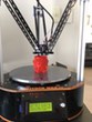
I'm doing a presentation on 3D printing and how I developed a functioning 3D printed fly reel at the American Museum of Fly Fishing in VT this Saturday. I'll be doing live demonstrations all day too. I wanted to print something that I can give away to the kids in attendance so I designed this little trout (about 3" long) that I can print 3-up in about 6 minutes. I am printing a bunch (>100) to take with me in various colors. Here are a couple:
[img]http://mhackney.zenfolio.com/img/s3/v8/ ... 3906-3.jpg[/img]
The trout on top is my standard KISS 4 perimeter with 33% curved infill. It makes for a "fishy" looking part.
I recently started exploring Simplify3D and ran into some issues with perimeters on my reel parts. So I backed off using it. But, with the new infill options in v3 (the primary reason I decided to give it another shot) I thought the trout might be a good thing to experiment with. The part on the bottom is S3D 30% wiggle infill at 90°. It came out quite nice. I also like the ability to orient the infill how I want. I'm doing some now at 30° and they look even more fish-scale like. I can also alternate layers (by any number) to do cross hatches like the KISS part.
The other thing I noticed is that S3D printed the perimeters (4) for the part and then filled it before moving on to the next. This is new behavior I believe and one of my issues with the earlier versions. They would print 1 perimeter for all parts, then go back and add a perimeter, etc. It is a challenge enough to get the angles for the fins to stick when all perimeters are laid down in succession but done one at a time almost always resulted in failure.
I am not a complete S3D convert due to the perimeter issue I reported in the S3D topic but I am continuing to experiment, tune and exploit its capabilities.
Sublime Layers - my blog on Musings and Experiments in 3D Printing Technology and Art
Start Here:
A Strategy for Successful (and Great) Prints
Strategies for Resolving Print Artifacts
The Eclectic Angler
Re: Mhackney's Rostock Max
Interesting fail. I took the S3D factory and aligned the wiggles 30°. These printed very nicely but I thought "hmm, alternating layers at +/- 30° should give an interesting effect" so I tried that. Simply added a new layer oriented to -30° in the infill tab and had at it. The parts were basically a fail. The infill is inconsistent and ugly, not nicely aligned like the photo above. Odd.
Sublime Layers - my blog on Musings and Experiments in 3D Printing Technology and Art
Start Here:
A Strategy for Successful (and Great) Prints
Strategies for Resolving Print Artifacts
The Eclectic Angler
Re: Mhackney's Rostock Max
Starting to get a nice little collection
[img]http://mhackney.zenfolio.com/img/s7/v15 ... 0987-3.jpg[/img]
I think I'm ultimately going to print one of these in every filament I have. Right now I have something like 60 different PLAs. For now, I'll finish up with some yellow, green, violet, black and perhaps some light sensitive that turns purple in the sun. Oh, and some glow in the dark (green, blue and red). I have too many filaments.
Sublime Layers - my blog on Musings and Experiments in 3D Printing Technology and Art
Start Here:
A Strategy for Successful (and Great) Prints
Strategies for Resolving Print Artifacts
The Eclectic Angler