Jrjones wrote:RollieRowland wrote:I figured I would upload a picture of the results.
0821150032.jpg
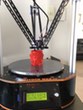
-Default mattercontrol settings (except nozzle size, which is 0.4mm - I have an e3d installed at the moment)
-Pressed print right after calibration, no z-height or any other modification. (Same calibration as the log from the previous post.)
-No bed heat or any form of adhesion -
the true test.
Also, sorry I forgot to oversize it to fit the 11 inches, I just used the default size. There is an area in the center where the plastic didn't stick to the bed, I am assuming it is mostly due to the cumulative dust/dirt of 2 weeks -
very bad, else just because of no form of adhesion.
Edit:
Thickness measurements of the print
XTower: inner 0.3 outer 0.31
YTower: inner 0.29 outer 0.3
ZTower: inner 0.3 outer 0.32
One more thing, I may need data from different printers for setting correct XY scaling. It is a very tedious task, and requires a lot of patience. However, it will help improve the programs accuracy in the XY dimensions. If you want to help, then let me know. You will need some things: calipers(accurate to 1/100th of a mm), FSRs, several sheets of paper, graphite, and maybe an hour of your time. If anyone is interested, I will write a reply describing how to properly get the data that I need.
I'm going to try the feeler gauge as a switch tomorrow, if it works than I would gladly help you out. Unless you need FSRs and think that the feeler gauge won't work.
Edit: I can't find where you mention it, but all you need to change in the firmware for the auto calibration is enabling the Z-probe correct?
Yes, you need to enable the Z-Probe and set the pin.
Here is my settings(using Rambo with the Z-Minimum pin as the probe):
#define FEATURE_Z_PROBE true
#define Z_PROBE_PIN 10
#define Z_PROBE_PULLUP true
#define Z_PROBE_ON_HIGH true
#define Z_PROBE_X_OFFSET 0
#define Z_PROBE_Y_OFFSET 0
#define Z_PROBE_WAIT_BEFORE_TEST false
#define Z_PROBE_SPEED 30
#define Z_PROBE_XY_SPEED 150
#define Z_PROBE_HEIGHT 39.91
#define Z_PROBE_START_SCRIPT ""
#define Z_PROBE_FINISHED_SCRIPT ""
Well I know this is most likely possible with methods other than FSRs, it is just that the FSRs are going to be the easiest. What I need is the measurements in the XY dimensions, how I measured was by putting paper on the plate, then scraping graphite onto my nozzle while probing in the center and near the tower. I don't absolutely need the heights, it would help but it's not neccessary. Without height measurements, the probe could be dropped just by the z-height on the printers display or in the host software(just so you don't break your bed by moving below the plate). I need about
49 data points from the printer for consistency. Then when I have at least 3 or 4 measurements from different printers, I can average them. This will give the best results for everyone.
Repeat for each tower:
1. Measure distance from the center of the plate to the tower being tested with horizontal radius, diagonal rod, and alpha rotation values at their defaults - XYZ offset does not need changed as it doesn't affect XY scaling.
2. Change delta radius X(dependent on the tower tested, Y, Z for the other towers) to 1, then measure the XY distance. Repeat for delta radius being set to 2,3,-1,-2,-3. Reset back to 0 after test.
3. Set Alpha Rotation A(specific to tower B,C for the others) to 211(specific to tower), then measure the XY distance. Repeat for 212, 213, 209, 208,207. Reset to 210 after test.
4. Set Horizontal Radius to 131(1 plus your default) and measure at the X, Y, and Z towers - all can be done at the same time. Repeat for 132, 133, 129, 128, 127. Reset back to 130.
5. Set Diagonal Rod to 270 (1 plus your default) and measure the X, Y, and Z towers - all at the same time. Repeat for 271, 272, 268, 267, 266.
The 4 points that are needed to measure(from tower to center for each test) for the Rostock Max V2:
Center - G1 Z0 X0 Y0
X Tower - G1 Z0 X-112.58 Y-65
Y Tower - G1 Z0 X112.58 Y-65
Z Tower - G1 Z0 Y130
For other printers replace the gcode with the appropriate sizes for your printer:
//Large = Your build diameter * 0.482;
//Medium = Your build diameter * 0.417;
//Small = Your build diameter * 0.241;
Center - G1 Z0 X0 Y0
X Tower - G1 Z0 X-Medium Y-Small
Y Tower - G1 Z0 XMedium Y-Small
Z Tower - G1 Z0 YLarge
With these measurements - when your EEProm has the defaults horizontal radius, diagonal rod, and alpha rotation - your first measurement
should be about 130.
If this wasn't clear enough, then let me know, and I will help.