
A thought in a different direction just came to me. Maybe we could leave the idlers alone, and use something like http://www.thingiverse.com/thing:51592 at the belt attachment on the carriage to put tension on the belt. This would add a few grams of weight to the carriage, but the only hardware it needs is a couple screws and locknuts and you can print the rest.
- dan
Another rostock max build
-
Eaglezsoar

- ULTIMATE 3D JEDI
- Posts: 7159
- Joined: Sun Apr 01, 2012 5:26 pm
Re: Another rostock max build
I am going to try a small eyebolt that the Idler screw passes through. The threads of the eyebolt would go through a rod at the top and be tightened with a locknut.
Simple and strong plus inexpensive. McMaster Carr has the small eyebolts with a 10-24 thread. The rod would be solid aluminum at about $6 per foot. The one foot
piece could be cut to handle all three axis on the printer. Each axis would cost about $4 for the rod piece, a longer idler screw and a nut for the eyebolt.
Re: Another rostock max build
My tensioner idea is on hold, so I continued on with the build.
I got the belt mounted. Some more stuff came in to finish off the wiring. Led indicators and knob from mouser electronics. I found these 60mm light rings on amazon, (http://www.amazon.com/Amico-White-Angel ... 60mm+white)I may use these to light up the hotend and make use of the light switch.
Time to get to work on the extruder assembly..
I got the belt mounted. Some more stuff came in to finish off the wiring. Led indicators and knob from mouser electronics. I found these 60mm light rings on amazon, (http://www.amazon.com/Amico-White-Angel ... 60mm+white)I may use these to light up the hotend and make use of the light switch.
My rostock build log http://forum.seemecnc.com/viewtopic.php?f=42&t=1228
Re: Another rostock max build
extruder done, wont be long now..My gears for the extruder were warped causing some binding. I had to do some sanding in order for it to spin freely. Very unusual. Seemed like the quality of those gears were lacking a bit but I got it to work. I didn't put a flat on the stepper motor shaft this time. Seemed like the press fit gear had plenty of bite to stay on the shaft.
I had more photos of the extruder assembly but it didn't depict the correct assembly in those photos so left those out, I didn't want to post incorrect assembly photos. I actually assembled it by ear, not looking at the instructions just to see if I could figure it out. Only following the steves extruder assembly pdf found here. http://seemecnc.org/download/RostockMAX/Assembly/
final steps next, installing the hot end and finishing up the rest of the wiring. I should be able to power this thing up soon..
Last edited by cambo3d on Fri Mar 22, 2013 11:30 am, edited 1 time in total.
My rostock build log http://forum.seemecnc.com/viewtopic.php?f=42&t=1228

Re: Another rostock max build
Here's a super cheap alternative to the whole problem.mhackney wrote:I'll keep everyone up to date on progress. Just waiting for parts to come in. Ironically, the cross rods are the one component I have completed! They are made of stock on hand on my mill where I can hold it firmly while drilling the holes.
They are from Walmart, for shelves, box of 50 for 8 bucks.
"Now you see why evil will always triumph! Because good is dumb." - Spaceballs
Re: Another rostock max build
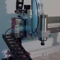
Finished up installing the hot end and most of the wiring along with the limit switches.
I wasn't too happy with the way the screw sits for the limit switches, Every hole in the mount was in a different spot. So it effected how the screw touches the limit switch. Considering the small area where the screw head needs to make contact with the limit switch. Position of these holes are critical for proper operation. They need to get better at accurately positioning these holes.
Photos of all three axis, every hole for the screw is in a different spot.
First photo, hole slightly on the slope of the mount
second photo, hole right in the middle of the slope. (where the slope meets the flat) This was the only one that hit my limit switch right on center. So IF you guys at seemecnc are reading this. THIS IS WHERE YOU NEED TO DRILL THE HOLE!
third photo, hole off to the left of the slope.
hotend installed and wired up, overall photo
I think i'm ready for a initial power up test and firmware upload tomorrow.. hopefully everything here goes smooth....
I wasn't too happy with the way the screw sits for the limit switches, Every hole in the mount was in a different spot. So it effected how the screw touches the limit switch. Considering the small area where the screw head needs to make contact with the limit switch. Position of these holes are critical for proper operation. They need to get better at accurately positioning these holes.
Photos of all three axis, every hole for the screw is in a different spot.
First photo, hole slightly on the slope of the mount
Last edited by cambo3d on Sun Jun 16, 2013 4:08 pm, edited 4 times in total.
My rostock build log http://forum.seemecnc.com/viewtopic.php?f=42&t=1228
-
Eaglezsoar
- ULTIMATE 3D JEDI
- Posts: 7159
- Joined: Sun Apr 01, 2012 5:26 pm
Re: Another rostock max build
Thanks for the great pictures, they are going to be a great help when I get to those points in my build.cambo3d wrote:extruder done, wont be long now..My gears for the extruder were warped causing some binding. I had to do some sanding in order for it to spin freely. Very unusual. Seemed like the quality of those gears were lacking a bit but I got it to work. I didn't put a flat on the stepper motor shaft this time. Seemed like the press fit gear had plenty of bite to stay on the shaft.
final steps next, installing the hot end and finishing up the rest of the wiring. I should be able to power this thing up soon..
Re: Another rostock max build
no problem, I wished more people posted there build logs on here. Because when I first started I was wondering whether I should buy this kit. Reading build logs from other people helps.
I still got a long ways to go, rostock max is finished but still have to do the calibration side of it and it doesn't look like its gonna be fun... after reading others post on here.
once I complete the build I plan on doing a complete review of the kit.
I still got a long ways to go, rostock max is finished but still have to do the calibration side of it and it doesn't look like its gonna be fun... after reading others post on here.
once I complete the build I plan on doing a complete review of the kit.
My rostock build log http://forum.seemecnc.com/viewtopic.php?f=42&t=1228
-
foshon

- Printmaster!
- Posts: 600
- Joined: Fri Mar 08, 2013 3:05 pm
- Location: Just to the right of SeeMeCNC
Re: Another rostock max build
Very nice machine sir! I have used some of your ideas so far and I appreciate the time it took to post your build.
Purple = sarcasm
Please do a board search before posting your question, many have been answered with very time consuming detail already.
Please do a board search before posting your question, many have been answered with very time consuming detail already.
Re: Another rostock max build
so here comes my first problem i cant get my lcd to display properly.
I've tried arduino 22 and 23, with marlin, then tried arduino 1.03 with repetier and the same happens on both firmwares. I've tried swapping the ribbon cables around, no joy.
I'm thinking my rambo is messed up or my lcd is messed up?
all i get is letters and boxes in marlin firmware
in repetier firmware
what am i doing wrong?
EDIT: PROBLEM FOUND http://forum.seemecnc.com/viewtopic.php ... &start=160
I've tried arduino 22 and 23, with marlin, then tried arduino 1.03 with repetier and the same happens on both firmwares. I've tried swapping the ribbon cables around, no joy.
I'm thinking my rambo is messed up or my lcd is messed up?
all i get is letters and boxes in marlin firmware
EDIT: PROBLEM FOUND http://forum.seemecnc.com/viewtopic.php ... &start=160
Last edited by cambo3d on Sun Mar 31, 2013 3:40 am, edited 1 time in total.
My rostock build log http://forum.seemecnc.com/viewtopic.php?f=42&t=1228
Re: Another rostock max build
thanks !foshon wrote:Very nice machine sir! I have used some of your ideas so far and I appreciate the time it took to post your build.
My rostock build log http://forum.seemecnc.com/viewtopic.php?f=42&t=1228
-
foshon
- Printmaster!
- Posts: 600
- Joined: Fri Mar 08, 2013 3:05 pm
- Location: Just to the right of SeeMeCNC
Re: Another rostock max build
Can't speak for Repetier, but the portion that is displaying in the marlin version is correct. It is showing your current temp / set point. I would lean toward connection issue as both screens have the same block pattern.cambo3d wrote:so here comes my first problem i cant get my lcd to display properly.
I've tried arduino 22 and 23, with marlin, then tried arduino 1.03 with repetier and the same happens on both firmwares. I've tried swapping the ribbon cables around, no joy.
I'm thinking my rambo is messed up or my lcd is messed up?
all i get is letters and boxes in marlin firmware in repetier firmware what am i doing wrong?
Purple = sarcasm
Please do a board search before posting your question, many have been answered with very time consuming detail already.
Please do a board search before posting your question, many have been answered with very time consuming detail already.
Re: Another rostock max build
does anyone have working lcd firmware, either repetier or marlin that could try.
My rostock build log http://forum.seemecnc.com/viewtopic.php?f=42&t=1228

Re: Another rostock max build
Polygonhells's firmware worked for my LCD 1st time. I had to build my own harness so it was even more amazing the thing worked first time! I'd never got Marlin to work with RAMBo but use it with my H-1s and LCD displays.
Sublime Layers - my blog on Musings and Experiments in 3D Printing Technology and Art
Start Here:
A Strategy for Successful (and Great) Prints
Strategies for Resolving Print Artifacts
The Eclectic Angler
Re: Another rostock max build
I've tried that firmware and still shows up the same way as marlin. Is there anything I need to do to arduino 1.03 before uploading it to the rambo? Or did you have to do anything to arduino 1.03?mhackney wrote:Polygonhells's firmware worked for my LCD 1st time. I had to build my own harness so it was even more amazing the thing worked first time! I'd never got Marlin to work with RAMBo but use it with my H-1s and LCD displays.
My rostock build log http://forum.seemecnc.com/viewtopic.php?f=42&t=1228
Re: Another rostock max build
Nope, it just worked. It is odd that it shows a 2 x 8 matrix correctly in the upper left corner of the display. There are actually directives in both firmwares to specify the matrix dimensions. Double check those. If that is correct, then I suspect the connector cable first and if that verifies Ok, the LCD might be a problem.
Sublime Layers - my blog on Musings and Experiments in 3D Printing Technology and Art
Start Here:
A Strategy for Successful (and Great) Prints
Strategies for Resolving Print Artifacts
The Eclectic Angler
Re: Another rostock max build
I just checked my ribbon cable, pin for pin, and they all have continuity. sigh.
My rostock build log http://forum.seemecnc.com/viewtopic.php?f=42&t=1228
Re: Another rostock max build
Go over the LCD board with a magnifier and look for loose/broken joints. I have 4 of these and they have been very reliable. Not to say a bad one might not squeak through though.
Since you seem to be getting partial display - and maybe enough to read the hotend temp, why not test that to see if the display works at least for that. Also, what happens when you use the selector knob to navigate the menus?
Since you seem to be getting partial display - and maybe enough to read the hotend temp, why not test that to see if the display works at least for that. Also, what happens when you use the selector knob to navigate the menus?
Sublime Layers - my blog on Musings and Experiments in 3D Printing Technology and Art
Start Here:
A Strategy for Successful (and Great) Prints
Strategies for Resolving Print Artifacts
The Eclectic Angler
Re: Another rostock max build
selector knob seems to work but display only shows those two lines, sometimes random characters, sometimes just two lines of white boxes across the display.
I can scroll up and down in those two lines, I can change feedrate using the knob, I push on the knob and it beeps.
the temperature that it displays seem to change when i change the temperature.
I have looked over the back of the board, I see no obvious problems
and on a side note while trying to take the lcd back out, i broke the angle mounts for it. It didn't help that used wood glue to help hold the mount together. sigh.
My rostock build log http://forum.seemecnc.com/viewtopic.php?f=42&t=1228
-
MorbidSlowBurn

- Printmaster!
- Posts: 169
- Joined: Sun Mar 03, 2013 5:33 pm
Re: Another rostock max build
I know you did a ring out on the pins but did you check to make sure adjacent pins weren't shorted. Don't think that will cause the issue but never know.
Re: Another rostock max build
I'm sending my lcd back to seemecnc for replacement.
but in the meantime. I wanted to take some temperature readings with my thermocouple meter.
here are the results. what do you guys think of this? what are your opinions?
the average temperature is the difference between the aluminum and brass parts of the nozzle.
From this chart it doesn't look like i'll be able to get the brass nozzle to 230, because aluminum temp always being higher and without damaging the peek.
on another note:
this bed rocks at 24v it heated up to 110. in a matter of minutes. Next to do test is to see how much current is exactly being drawn at 24v at the various temps on the heat bed
but in the meantime. I wanted to take some temperature readings with my thermocouple meter.
here are the results. what do you guys think of this? what are your opinions?
From this chart it doesn't look like i'll be able to get the brass nozzle to 230, because aluminum temp always being higher and without damaging the peek.
on another note:
this bed rocks at 24v it heated up to 110. in a matter of minutes. Next to do test is to see how much current is exactly being drawn at 24v at the various temps on the heat bed
Last edited by cambo3d on Sat Mar 23, 2013 2:17 pm, edited 7 times in total.
My rostock build log http://forum.seemecnc.com/viewtopic.php?f=42&t=1228
Re: Another rostock max build
cambo3D, nice work. Looking at the heated bed section at the top, it shows that the reading the thermistor is sending to the controller is being held within a 1/2 degree C for all but the 61°C case - pretty nice control.
Measuring temp accurately with a thermocouple is a challenge. Did you insulate over the top of the thermocouple probe for instance?
A better way to check the thermistor against a thermocouple is to use boiling water - 100°C. If you stick the thermocouple and thermistor in the same pan of boiling water (careful of shorts if its a metal pan) they should both read 100°C. You can also use higher temperature fluids like silicone oil, etc to check calibration at higher temps. With this info, you can then calibrate your thermistor - given the thermocouple reading is accurate.
Sublime Layers - my blog on Musings and Experiments in 3D Printing Technology and Art
Start Here:
A Strategy for Successful (and Great) Prints
Strategies for Resolving Print Artifacts
The Eclectic Angler
-
foshon
- Printmaster!
- Posts: 600
- Joined: Fri Mar 08, 2013 3:05 pm
- Location: Just to the right of SeeMeCNC
Re: Another rostock max build
cambo3d wrote:I'm sending my lcd back to seemecnc for replacement.
but in the meantime. I wanted to take some temperature readings with my thermocouple meter.
here are the results. what do you guys think of this? what are your opinions?
the average temperature is the difference between the aluminum and brass parts of the nozzle.
Does the Aluminum temp at nozzle end is the bottom, top, or outside of the ring. I find it alarming to see the difference in those two measurments increase so much as temperature rises. Tells me either the thermocouple is having difficulty measuring the right temp or something is slowing hte transfer of heat between the alum and brass. How long did you let it soak for the measurments?
Purple = sarcasm
Please do a board search before posting your question, many have been answered with very time consuming detail already.
Please do a board search before posting your question, many have been answered with very time consuming detail already.
Re: Another rostock max build
Does the Aluminum temp at nozzle end is the bottom, top, or outside of the ring. I find it alarming to see the difference in those two measurments increase so much as temperature rises. Tells me either the thermocouple is having difficulty measuring the right temp or something is slowing hte transfer of heat between the alum and brass. How long did you let it soak for the measurments?[/quote]
the measurement taken at the nozzle was inside the other thermistor hole.
the measurement taken at the nozzle was inside the other thermistor hole.
My rostock build log http://forum.seemecnc.com/viewtopic.php?f=42&t=1228
-
foshon
- Printmaster!
- Posts: 600
- Joined: Fri Mar 08, 2013 3:05 pm
- Location: Just to the right of SeeMeCNC
Re: Another rostock max build
cambo3d wrote:Does the Aluminum temp at nozzle end is the bottom, top, or outside of the ring. I find it alarming to see the difference in those two measurments increase so much as temperature rises. Tells me either the thermocouple is having difficulty measuring the right temp or something is slowing hte transfer of heat between the alum and brass. How long did you let it soak for the measurments?
the measurement taken at the nozzle was inside the other thermistor hole.[/quote]
If you don't have plastic in there yet, pull out your tube and stick the probe right down the shaft to the tip. Let the nozzle soak at temp until it stabalizes.
Purple = sarcasm
Please do a board search before posting your question, many have been answered with very time consuming detail already.
Please do a board search before posting your question, many have been answered with very time consuming detail already.