ApacheXMD's Build
Re: ApacheXMD's Build
So I'm continuing on ahead while I await new laser cut parts. I am trying to sand the arms to fit the u joints and am having a hell of a time. Did anyone find a good way to pop to joint OUT of the arms? Having to pry them out repeatedly to test fit after sanding the arms is really a challenge. I'm tring very hard not to gouge the face of the joints with a screwdriver but i cant figure out a graceful to get them out over and over again.
-
MorbidSlowBurn

- Printmaster!
- Posts: 169
- Joined: Sun Mar 03, 2013 5:33 pm
Re: ApacheXMD's Build
I recommend using a plastic scraper. You don't want to put any burrs or gouges in the pieces. I never found a way that was easy but I mostly twist the arms to get one edge to lift. I then use the plastic scraper to lift it off the post. The second side I do almost the same. Not easy to describe.
Also remember to have the screws tightened close to the final tightness as they can distort the plastic where you are sanding. You can have a great joint, then tighten everything down just to cause binding again.
Also remember to have the screws tightened close to the final tightness as they can distort the plastic where you are sanding. You can have a great joint, then tighten everything down just to cause binding again.
Re: ApacheXMD's Build
be ready for lots O sandin fun, it took me 3hours to get a some what smooth motion, and still need to do more, just haven't gotten around to it yet.
My rostock build log http://forum.seemecnc.com/viewtopic.php?f=42&t=1228
Re: ApacheXMD's Build
Yeah i know its going to no fun. I spent about half an hour sanding one arm. And its still way too tight. Did you guys sand the hot end platform and cheapskate sides first, to fit the ujoint pieces? Starting with the arms is turning out to be very difficult, in both snapping in a u joint and removal. Maybe if they were already fitted to the platform and cheapskates i'd have better leverage.
Re: ApacheXMD's Build
I dont know if it really matters which one you do first, but the arms takes quite a bit of time to complete,
My rostock build log http://forum.seemecnc.com/viewtopic.php?f=42&t=1228
-
MorbidSlowBurn
- Printmaster!
- Posts: 169
- Joined: Sun Mar 03, 2013 5:33 pm
Re: ApacheXMD's Build
I had my entire rostock built so I started with the cheapskates and platform. I removed one arm at a time so I made sure the arm went back into the same ujoints with the same side facing up. After that then I attacked the arms. After the first couple I got into a pretty good rhythm. But never found an easy way to separate the arms from the ujoints.
Re: ApacheXMD's Build
I received new laser cut parts from SeemeCNC. They really took care of me after I contacted them about the skewed parts. I appreciate their actions thus far.
And I can tell you now, that the parts I recieved are almost deadnuts perfect. I measured every vertical piece again and they were all within .3mm of each other. I built the base tonight and I'm happy to report that it's looking pretty good:
Measuring with a straight edge across two of the t-slot locations, it's dead flat. Across the third there is a slight perceptible bump in the middle; the straight edge lifts up about .2mm. Not perfect, but pretty darn good in my eyes. And there's no wobble of the whole base when it's sitting on the table!
These new parts also went together a million times easier! There were only 3 or 4 nut slots that had to be slightly enlarged. And two slots in the base for the verticals had to be touched up. But other than that it fit together much smoother than the first time around. The top went on like butter too. Only fought it for about 2 minutes and it slipped right on!
Oh, and it looks like SeeMeCNC has updated a few of the parts in the laser cut set.
The electronics mount/door is now completely blank. And I didn't get a picture of it, but one side of the tilted LCD stand off pieces isn't labeled nor cut out for the SD card slot. Before, both sides were labeled and cut for an SD card slot.
That's all I've noticed so far; if I see anything else different I'll post it here.
And I can tell you now, that the parts I recieved are almost deadnuts perfect. I measured every vertical piece again and they were all within .3mm of each other. I built the base tonight and I'm happy to report that it's looking pretty good:
- Flat table top
These new parts also went together a million times easier! There were only 3 or 4 nut slots that had to be slightly enlarged. And two slots in the base for the verticals had to be touched up. But other than that it fit together much smoother than the first time around. The top went on like butter too. Only fought it for about 2 minutes and it slipped right on!
Oh, and it looks like SeeMeCNC has updated a few of the parts in the laser cut set.
- Blank Electronics door
That's all I've noticed so far; if I see anything else different I'll post it here.
Re: ApacheXMD's Build
makes me think i should consider returning mine for replacement, though not as bad as yours originally, still affects calibration.. i think.
I may take it apart and take measurements like you did to verify.
I may take it apart and take measurements like you did to verify.
My rostock build log http://forum.seemecnc.com/viewtopic.php?f=42&t=1228
Re: ApacheXMD's Build
Got most of the mechanical assembly done. Now need to get started on the wiring.
Would it be wise to have the heated bed power on a toggle switch? Once a few layers are printed and there is good adhesion, is it safe to shut off the onyx?
Also does anyone know if the endstop switches have a common pin, ie ground or 5v? I'd like to run all my wiring up a single tower and want to minimize the number of wires needed.
Like others here I'm working on a BerryBot-style magnetic ball joint system. I'm using GeoMag construction toys It's kind of a cludge now but once the printer is calibrated the first real print will be replacement carriages and print head platform with divots for precise ball placement. Working on a model now.
The rods aren't done yet, the ones in the pictures are the GeoMag toy rods that came with the set. Testing range of motion looks promising, and this is with shorter rods than stock so motion is a little greater than what it will be with correct length rods
I'm also working on a tensioning sytem. I'm using these things I found at work.
I had to drill out the steel rivet to get what I want. I'll try them out when I get home and I'll post more pictures
- Mechanical done
Also does anyone know if the endstop switches have a common pin, ie ground or 5v? I'd like to run all my wiring up a single tower and want to minimize the number of wires needed.
Like others here I'm working on a BerryBot-style magnetic ball joint system. I'm using GeoMag construction toys It's kind of a cludge now but once the printer is calibrated the first real print will be replacement carriages and print head platform with divots for precise ball placement. Working on a model now.
- Carriage balls
- Platform balls
I'm also working on a tensioning sytem. I'm using these things I found at work.
- Drilled out fasteners

Re: ApacheXMD's Build
LOL, good to see someone else trying for this too. The 15mm bearings fit perfect don't they?
Geomag, That's the name I could not think of.
I'm starting to think that having the bearings on the top edge of the build plateform in cup will produce a better end result because this allows for better range of movements.
I also encountered an odd overshoot behavior when trying to use the geomag ends. I'm curious how yours turn out.
I'm not sure of what your referring to when you say tensioning system. Or what the fasteners are for you show?
"Now you see why evil will always triumph! Because good is dumb." - Spaceballs
Re: ApacheXMD's Build
overshoot, or slipping of the magnet on the ball is a concern for me.
I like the idea of having the ball there, for easier assembly, I even looked for some that had tapped holes so that a rod could be screwed directly into it.
build looks like its coming along nicely
the endstops need both wires for it to work properly, you would still need to run all the wires for them in order for you to home and zero properly. Can't really combine wires here because they operate separately but you could still possibly run all the wires up one tower, i think there's room in there.
My rostock build log http://forum.seemecnc.com/viewtopic.php?f=42&t=1228
-
MorbidSlowBurn
- Printmaster!
- Posts: 169
- Joined: Sun Mar 03, 2013 5:33 pm
Re: ApacheXMD's Build
Apache- You don't really need a toggle on the Onyx. If you are concerned and want to shut it down, most slicers have a setting that lets you drop the temp after the first layer or so.
Re: ApacheXMD's Build
The GeoMag spheres are actually only 12.7mm in diameter, 0.5inches. I have them mounted to the outer extremes of the slot. They're currently held in place with hot glue for ease of removal later on. I read about your experiments with the magnetic toys, and was wondering if your prints did any better on slow speeds?Flateric wrote:LOL, good to see someone else trying for this too. The 15mm bearings fit perfect don't they?
Geomag, That's the name I could not think of.
I'm starting to think that having the bearings on the top edge of the build plateform in cup will produce a better end result because this allows for better range of movements.
I also encountered an odd overshoot behavior when trying to use the geomag ends. I'm curious how yours turn out.
I'm not sure of what your referring to when you say tensioning system. Or what the fasteners are for you show?
The fastener bits are for a belt tensioning system. Sorry for the vagueness.
I think I've seen some balls with a welded stud on them already, something like this.cambo3d wrote:overshoot, or slipping of the magnet on the ball is a concern for me.
I like the idea of having the ball there, for easier assembly, I even looked for some that had tapped holes so that a rod could be screwed directly into it.
build looks like its coming along nicely
the endstops need both wires for it to work properly, you would still need to run all the wires for them in order for you to home and zero properly. Can't really combine wires here because they operate separately but you could still possibly run all the wires up one tower, i think there's room in there.
According to Geneb's assembly instructions, we're using NC switches. I took a look at the Rambo schematic, and it looks like we're pulling the endstop pins low to ground until we hit an endstop which opens the circuit. So I think I can daisy chain the ground from switch to switch. Am I understanding it correctly?
MorbidSlowBurn wrote:Apache- You don't really need a toggle on the Onyx. If you are concerned and want to shut it down, most slicers have a setting that lets you drop the temp after the first layer or so.
That should work ok when printing from a PC, but I was planning on doing some prints from the SD card independent of a computer. In that case I might want to have manual control of the heated bed.
I didn't get much done tonight, just mounted the end stop switches and started assembling my hot end. It's hard to get time to work on the hobbies with a 1 year old. He's always top priority.
-
MorbidSlowBurn
- Printmaster!
- Posts: 169
- Joined: Sun Mar 03, 2013 5:33 pm
Re: ApacheXMD's Build
If you set the slicer up, the temperature is embedded in the g-code. It doesn't matter if you print from computer or SD card.
-
Polygonhell
- ULTIMATE 3D JEDI
- Posts: 2417
- Joined: Mon Mar 26, 2012 1:44 pm
- Location: Redmond WA
Re: ApacheXMD's Build
This is only partly true.MorbidSlowBurn wrote:If you set the slicer up, the temperature is embedded in the g-code. It doesn't matter if you print from computer or SD card.
While you can do it that way most slicers don'r add the commands if you set the temperature to 0 when slicing.
I commonly slice with bed temperature set to 0 and then manually set the bed temperature before starting.
Printer blog http://3dprinterhell.blogspot.com/
Re: ApacheXMD's Build
"According to Geneb's assembly instructions, we're using NC switches. I took a look at the Rambo schematic, and it looks like we're pulling the endstop pins low to ground until we hit an endstop which opens the circuit. So I think I can daisy chain the ground from switch to switch. Am I understanding it correctly?"
now I see what you meant that should work then. Looking at the schematic they do share the same ground.
now I see what you meant that should work then. Looking at the schematic they do share the same ground.
My rostock build log http://forum.seemecnc.com/viewtopic.php?f=42&t=1228
-
MorbidSlowBurn
- Printmaster!
- Posts: 169
- Joined: Sun Mar 03, 2013 5:33 pm
Re: ApacheXMD's Build
True about setting the temp to 0. But why not set it to 10. Anything setting below room temperature and the heated bed should not turn on.
Re: ApacheXMD's Build
Thanks for the info about the gcode. This being my first printer I am as of yet unfamiliar with gcode.
Oh one other thing, is anyone else having problems finding an allen key to fit the 1/4-20 screws for the t nuts? 4mm is too big, 9/64 is too small. They're measuring out to be about 3.8mm and i dont think thats a standard size. I have them as tight as I dare with a 9/64 but i think I'm going to grind down a 4mm allen to fit.
Oh one other thing, is anyone else having problems finding an allen key to fit the 1/4-20 screws for the t nuts? 4mm is too big, 9/64 is too small. They're measuring out to be about 3.8mm and i dont think thats a standard size. I have them as tight as I dare with a 9/64 but i think I'm going to grind down a 4mm allen to fit.
-
Polygonhell
- ULTIMATE 3D JEDI
- Posts: 2417
- Joined: Mon Mar 26, 2012 1:44 pm
- Location: Redmond WA
Re: ApacheXMD's Build
Because if you use M190 to set the heated bed temperature which some slicers do, it waits for the temperature to be with a small window of the target temperature and your print won't start.MorbidSlowBurn wrote:True about setting the temp to 0. But why not set it to 10. Anything setting below room temperature and the heated bed should not turn on.
Printer blog http://3dprinterhell.blogspot.com/
-
MorbidSlowBurn
- Printmaster!
- Posts: 169
- Joined: Sun Mar 03, 2013 5:33 pm
Re: ApacheXMD's Build
@polygonhell- I thought this was true for the start of the print. But the question was stated that after the print started would it be ok to use a switch to turn off the bed. I proposed setting the first layer temp at the target start temp in the slicer which apache is already doing, after that using the setting in the slicer to drop it down to a lower temp possibly room temp or below to keep the power supplied to the bed off. Correct me if I am wrong but I thought as long as the print had started the set temp in the higher layers could be dropped and not affect the print, even if it doesn't drop to the lower temp.
-
Polygonhell
- ULTIMATE 3D JEDI
- Posts: 2417
- Joined: Mon Mar 26, 2012 1:44 pm
- Location: Redmond WA
Re: ApacheXMD's Build
Yes it's fine unless there are additional M140 or M190's in the GCode.MorbidSlowBurn wrote:@polygonhell- I thought this was true for the start of the print. But the question was stated that after the print started would it be ok to use a switch to turn off the bed. I proposed setting the first layer temp at the target start temp in the slicer which apache is already doing, after that using the setting in the slicer to drop it down to a lower temp possibly room temp or below to keep the power supplied to the bed off. Correct me if I am wrong but I thought as long as the print had started the set temp in the higher layers could be dropped and not affect the print, even if it doesn't drop to the lower temp.
You can just send an M140 S0 while printing it won't interrupt the print, or use the LCD to turn it down to 0.
Printer blog http://3dprinterhell.blogspot.com/
Re: ApacheXMD's Build
Here's what I'm trying out for tensioning.
I know it's not ideal as it requires quite long lengths of 6-32 screws. I'm thinking about drilling out the bearing spacers to something more substantial like 10-32.
So i was finishing up the build and got to the electronics. I decided to mount the LCD somewhat unconventionally since i couldnt figure out how to install the angled mounts and the faceplate.
I found some RC car parts and some brass PC board standoffs from my PC building days.
The ball studs were installed into holes that were drilled into the side of the faceplate. Mating ball sockets were installed in the door. And a big shiny knob from RatShack was installed on the clicky shaft.
Finally, it was time to level out the axes and try a print:
As you can see the infill doesn't quite touch the perimeter. Not sure what it is because the infill looks like it's the perimeter that's getting too wide. Infill looks to be where it's supposed to be. I have to double check my extrusion settings. I'm still fumbling through the software right now but that part was sliced with kisslicer with mhackney's settings. Printed with abs at 235c. Seemed to need that much heat to get decent flow. I'll cross check the temps with my thermocouple. I was a little worried about burning th house down when i first fired up the rostock but so far so good!
Still have lots to do but excited to have a halfway decent start
- Tensioner
So i was finishing up the build and got to the electronics. I decided to mount the LCD somewhat unconventionally since i couldnt figure out how to install the angled mounts and the faceplate.
I found some RC car parts and some brass PC board standoffs from my PC building days.
- Standoffs and ball stud
- Radioshack knob
- Lcd mounted
- First print
Still have lots to do but excited to have a halfway decent start
Re: ApacheXMD's Build
Printed out a hollow single wall cube next.
Turned out pretry good. Wall thickness measured a little thick at 0.61mm so I adjusted the flow tweak in Kisslicer. Also the 20mm sides measured a little shy at 19.6mm so i also adjusted the arm length in firmware.
Third print measured a little better
- 2nd print, single wall
- Third print, adjusted extrusion width
Re: ApacheXMD's Build
i was wondering how to adjust the thickness in kisslicer. now i know. great idea for the lcd mount.
My rostock build log http://forum.seemecnc.com/viewtopic.php?f=42&t=1228
Re: ApacheXMD's Build
Just to update my build thread. I was having some strange layer shifting issues but I got that resolved. Turns out it was an issue with stepper wiring being in too close proximity to endstop wiring.
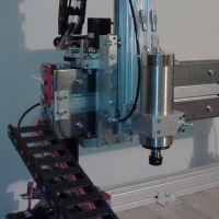
I saw the new ezstruder, as well as the top mount for it at the Bay Area Makerfaire. I liked not having the spool hanging off the side, so I came up with my own solution for the spool and extruder.
Here are some pictures of the current setup.
Please excuse the messiness of the wiring and generous application of zip ties.
Ez struder is attached to the laser cut pieces that came with it. It's bolted to a piece of aluminum square tube that's bolted to the old spool axle pieces. This allows it to slip onto the top and bottom plates of the printer.
The spool itself is just sitting on a random CD-ROM drive motor that was in my parts drawer. It acts as a bearing and lets the spool spin with very little friction. There's a PTFE tube that guides the filament down from the spool into the entrance of the EZStruder. To aid with retractions, I tried to calculate the position of the EZStruder to minimize the length of the required bowden tube. I've got it down to about 18" now. Mounting the extruder up high means a longer bowden tube. With the EZstruder "shooting" sideways, I still have full range of motion even with the shorter bowden. I've predrilled some extra holes in the aluminum tube with hopes of a dual extruder setup in the future. Imagine a second EZstruder right above the first one
I'm still playing with retraction settings, but it's going well so far. The EZstruder is much nicer than the stock extruder. Retractions don't sound like rocks in a tin can.
I saw the new ezstruder, as well as the top mount for it at the Bay Area Makerfaire. I liked not having the spool hanging off the side, so I came up with my own solution for the spool and extruder.
Here are some pictures of the current setup.
Ez struder is attached to the laser cut pieces that came with it. It's bolted to a piece of aluminum square tube that's bolted to the old spool axle pieces. This allows it to slip onto the top and bottom plates of the printer.
The spool itself is just sitting on a random CD-ROM drive motor that was in my parts drawer. It acts as a bearing and lets the spool spin with very little friction. There's a PTFE tube that guides the filament down from the spool into the entrance of the EZStruder. To aid with retractions, I tried to calculate the position of the EZStruder to minimize the length of the required bowden tube. I've got it down to about 18" now. Mounting the extruder up high means a longer bowden tube. With the EZstruder "shooting" sideways, I still have full range of motion even with the shorter bowden. I've predrilled some extra holes in the aluminum tube with hopes of a dual extruder setup in the future. Imagine a second EZstruder right above the first one
I'm still playing with retraction settings, but it's going well so far. The EZstruder is much nicer than the stock extruder. Retractions don't sound like rocks in a tin can.