Foshon's Big and Tall
-
Polygonhell
- ULTIMATE 3D JEDI
- Posts: 2417
- Joined: Mon Mar 26, 2012 1:44 pm
- Location: Redmond WA
Re: Foshon's Big and Tall
It does affect the linearity of the carriage because the angle it's pulling at changes with position, so a 1mm move of the belt no longer moves the carriage 1mm. Having said that given the length of the belt and the angles involved I doubt it's significant enough for it not to be swamped by other factors.
Printer blog http://3dprinterhell.blogspot.com/
-
foshon

- Printmaster!
- Posts: 600
- Joined: Fri Mar 08, 2013 3:05 pm
- Location: Just to the right of SeeMeCNC
Re: Foshon's Big and Tall
As for the belt rubbing, I took the following pictures. In the first one the belt is not touching the base. The second shows the distance from the base at this point.
[img]http://farm9.staticflickr.com/8262/8628618240_7ed9cab29d_n.jpg[/img]
Untitled by foshon, on Flickr
[img]http://farm9.staticflickr.com/8101/8627519415_dce035b35e_n.jpg[/img]
Untitled by foshon, on Flickr
[img]http://farm9.staticflickr.com/8262/8628618240_7ed9cab29d_n.jpg[/img]
Untitled by foshon, on Flickr
[img]http://farm9.staticflickr.com/8101/8627519415_dce035b35e_n.jpg[/img]
Untitled by foshon, on Flickr
Purple = sarcasm
Please do a board search before posting your question, many have been answered with very time consuming detail already.
Please do a board search before posting your question, many have been answered with very time consuming detail already.
-
foshon
- Printmaster!
- Posts: 600
- Joined: Fri Mar 08, 2013 3:05 pm
- Location: Just to the right of SeeMeCNC
Re: Foshon's Big and Tall
Polygonhell wrote:It does affect the linearity of the carriage because the angle it's pulling at changes with position, so a 1mm move of the belt no longer moves the carriage 1mm. Having said that given the length of the belt and the angles involved I doubt it's significant enough for it not to be swamped by other factors.
I guess I'm confused. The movement of the carriage is effectively controled by the the movement of the belt. The belt to motor interface angle never changes as it is set by the angle of the inner idler bearing to the motor shaft. Don't these pivot points make the subtle change in the angle of the belt to carriage interface over the usuable printing length of the carriages movement a moot point?
Edit:
Thinking abotu what you said and looking at the installation further, there is really no reason the belt cant be pulled through the original hole and the the clamps used in the same way. It would still allow for pull tensioning, which I have found to be more then enough to break stuff.
Last edited by foshon on Sun Apr 07, 2013 1:50 pm, edited 1 time in total.
Purple = sarcasm
Please do a board search before posting your question, many have been answered with very time consuming detail already.
Please do a board search before posting your question, many have been answered with very time consuming detail already.
Re: Foshon's Big and Tall
Even the belt tension is changing over the length. I wouldn't operate it like this.
-
foshon
- Printmaster!
- Posts: 600
- Joined: Fri Mar 08, 2013 3:05 pm
- Location: Just to the right of SeeMeCNC
Re: Foshon's Big and Tall
aehM_Key wrote:Even the belt tension is changing over the length. I wouldn't operate it like this.
Technically the belt tension changes every timne you move the belt, with any mounting system. If you think locking the belt tensioner with hardware and mechanically stretching belt is a better option, have at it.
Purple = sarcasm
Please do a board search before posting your question, many have been answered with very time consuming detail already.
Please do a board search before posting your question, many have been answered with very time consuming detail already.
Re: Foshon's Big and Tall
Sorry, I can't follow you.
It changes because of the geometry if you fix the belt like this http://www.flickr.com/photos/94200223@N06/8625860464/ instead of the original position.
It changes because of the geometry if you fix the belt like this http://www.flickr.com/photos/94200223@N06/8625860464/ instead of the original position.
-
foshon
- Printmaster!
- Posts: 600
- Joined: Fri Mar 08, 2013 3:05 pm
- Location: Just to the right of SeeMeCNC
Re: Foshon's Big and Tall
aehM_Key wrote:Sorry, I can't follow you.
It changes because of the geometry if you fix the belt like this http://www.flickr.com/photos/94200223@N06/8625860464/ instead of the original position.
I agree but I think the change is negliable due to the placement of the two idler bearings surrounding the motor. The geometry of the belt past the idler on the inner side of the motor cavity is negated partially by its contact with the belt. I could pull the belt over that pulley at a 90 degree angle and still maintain the correct angle between the inner idler and the motor. As long as one doesn't move the belt closer to the extrusion the contact angle is the same regardless. The tension may change slightly, but if at the point it is most loose it is tight enough to maintain step integrity, then it doesn't matter.
I re-routed the belt behind the carriage in the original fashion. The clamp works the same way. Becuase the tension issue does concern me.
Purple = sarcasm
Please do a board search before posting your question, many have been answered with very time consuming detail already.
Please do a board search before posting your question, many have been answered with very time consuming detail already.
-
foshon
- Printmaster!
- Posts: 600
- Joined: Fri Mar 08, 2013 3:05 pm
- Location: Just to the right of SeeMeCNC
Re: Foshon's Big and Tall
After looking at the original clamp I found this.
[img]http://farm9.staticflickr.com/8101/8627987901_7e2b5d4883_n.jpg[/img]
Untitled by foshon, on Flickr
The belt supplied with the MAX is on top. It is a GT2 belt. The belt on the bottom is a T5 that I originally used on my Prusa. It is clear that the clamps were designed for those belts. See this photo:
[img]http://farm9.staticflickr.com/8103/8629118638_7302037097_n.jpg[/img]
Untitled by foshon, on Flickr
This is the supplied GT2 belt shown on the clamp:
[img]http://farm9.staticflickr.com/8537/8628089625_dda236e1d3_n.jpg[/img]
Untitled by foshon, on Flickr
This is the clamp I designed (altered another design which reminds me I need to fix the thing page) with the belt next to it:
[img]http://farm9.staticflickr.com/8124/8628095351_bd35ba7ed5_n.jpg[/img]
Untitled by foshon, on Flickr
And a shot of the interface between the two:
[img]http://farm9.staticflickr.com/8242/8628099189_8bd73c99b8_n.jpg[/img]
Untitled by foshon, on Flickr
Purple = sarcasm
Please do a board search before posting your question, many have been answered with very time consuming detail already.
Please do a board search before posting your question, many have been answered with very time consuming detail already.
-
foshon
- Printmaster!
- Posts: 600
- Joined: Fri Mar 08, 2013 3:05 pm
- Location: Just to the right of SeeMeCNC
Re: Foshon's Big and Tall
The point of doing this was to allow for tensioning of the belt by pulling it tight before tightinging the clamp. A function it performs very well.
Here is a shot of the clamp after mounting with the correct geometry:
[img]http://farm9.staticflickr.com/8122/8629256678_25de4f4a51_n.jpg[/img]
Untitled by foshon, on Flickr
Here is a shot of the clamp after mounting with the correct geometry:
[img]http://farm9.staticflickr.com/8122/8629256678_25de4f4a51_n.jpg[/img]
Untitled by foshon, on Flickr
Purple = sarcasm
Please do a board search before posting your question, many have been answered with very time consuming detail already.
Please do a board search before posting your question, many have been answered with very time consuming detail already.
Re: Foshon's Big and Tall
i never understood why they used the clamps they provided in the kit, they know its for a different belt. even say it in the instructions. If they used one that fits it better maybe we wouldn't be damaging our belts on installation.
My rostock build log http://forum.seemecnc.com/viewtopic.php?f=42&t=1228
-
Eaglezsoar

- ULTIMATE 3D JEDI
- Posts: 7159
- Joined: Sun Apr 01, 2012 5:26 pm
Re: Foshon's Big and Tall
Why not make one in two pieces, the first piece would have the proper teeth spacing for the Rostock belts and the back piece would just be flat with the slots.
It would work identical to the SeemeCNC except the teeth would fit and it wouldn't be foldable. I doubt you could fold abs or pla.
A good project for you, brother Foshon. It would be something new for you to fondle.
Carl
It would work identical to the SeemeCNC except the teeth would fit and it wouldn't be foldable. I doubt you could fold abs or pla.
A good project for you, brother Foshon. It would be something new for you to fondle.
Carl
Last edited by Eaglezsoar on Sun Apr 07, 2013 4:38 pm, edited 1 time in total.
-
Eaglezsoar
- ULTIMATE 3D JEDI
- Posts: 7159
- Joined: Sun Apr 01, 2012 5:26 pm
Re: Foshon's Big and Tall
Because they found them cheaper off the shelf somewhere so they wouldn't have to produce them.cambo3d wrote:i never understood why they used the clamps they provided in the kit, they know its for a different belt. even say it in the instructions. If they used one that fits it better maybe we wouldn't be damaging our belts on installation.
Carl
-
foshon
- Printmaster!
- Posts: 600
- Joined: Fri Mar 08, 2013 3:05 pm
- Location: Just to the right of SeeMeCNC
Re: Foshon's Big and Tall
The front of the cheapskate makes for a decent backing. Without the back you can attach the clamp, slide the belt through, and then finish tightning while tensioning the belt. I was looking into making a tensioning clamp like in the link, but it doesn't fit well enough to remain usable.Eaglezsoar wrote:Why not make one in two pieces, the first piece would have the proper teeth spacing for the Rostock belts and the back piece would just be flat with the slots.
It would work identical to the SeemeCNC except the teeth would fit and it wouldn't be foldable. I doubt you could fold abs or pla.
A good project for you, brother Foshon. It would be something new for you to fondle.
Carl
http://www.thingiverse.com/thing:20411
Purple = sarcasm
Please do a board search before posting your question, many have been answered with very time consuming detail already.
Please do a board search before posting your question, many have been answered with very time consuming detail already.
-
foshon
- Printmaster!
- Posts: 600
- Joined: Fri Mar 08, 2013 3:05 pm
- Location: Just to the right of SeeMeCNC
Re: Foshon's Big and Tall
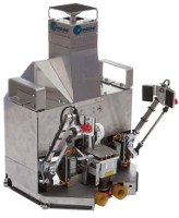
Here is my hot bed. It is a aluminum circle that I cut with a jigsaw. Didn't turn out to bad. I stuck a 24V kapton heater on the back of it. It ohms out to 2.7, and my 24V PS is tuned down to 20 volts, so roughly 7.77 amps through the RAMBo. Should be good. It had no issues hitting 80 C and got there plenty fast for me, no radiant insulation yet.
[img]http://farm9.staticflickr.com/8250/8632107732_8117d8345c_n.jpg[/img]
Untitled by foshon, on Flickr
[img]http://farm9.staticflickr.com/8250/8632107732_8117d8345c_n.jpg[/img]
Untitled by foshon, on Flickr
Purple = sarcasm
Please do a board search before posting your question, many have been answered with very time consuming detail already.
Please do a board search before posting your question, many have been answered with very time consuming detail already.
-
Polygonhell
- ULTIMATE 3D JEDI
- Posts: 2417
- Joined: Mon Mar 26, 2012 1:44 pm
- Location: Redmond WA
Re: Foshon's Big and Tall
I'd check how flat that Al is.
Unless it's a cast plate (read expensive) there is a very good chance it's not very flat.
The heated bed on my first printer is similar to your design and I really didn't realize how not flat it was until I put a piece of glass on top of it.
Unless it's a cast plate (read expensive) there is a very good chance it's not very flat.
The heated bed on my first printer is similar to your design and I really didn't realize how not flat it was until I put a piece of glass on top of it.
Printer blog http://3dprinterhell.blogspot.com/
-
Eaglezsoar
- ULTIMATE 3D JEDI
- Posts: 7159
- Joined: Sun Apr 01, 2012 5:26 pm
Re: Foshon's Big and Tall
What is the size of that kapton heater and the diameter of the aluminum? I assume you gave up on the Onyx.foshon wrote:Here is my hot bed. It is a aluminum circle that I cut with a jigsaw. Didn't turn out to bad. I stuck a 24V kapton heater on the back of it. It ohms out to 2.7, and my 24V PS is tuned down to 20 volts, so roughly 7.77 amps through the RAMBo. Should be good. It had no issues hitting 80 C and got there plenty fast for me, no radiant insulation yet.
[img]http://farm9.staticflickr.com/8250/8632107732_8117d8345c_n.jpg[/img]
Untitled by foshon, on Flickr
That heater looks like it came from Trinity, did I guess right?
Carl
-
foshon
- Printmaster!
- Posts: 600
- Joined: Fri Mar 08, 2013 3:05 pm
- Location: Just to the right of SeeMeCNC
Re: Foshon's Big and Tall
Ultibots I believe, but they are identical. The aluminium is a circle (closely related to, my jigsaw skills are less than optimal) the diameter of the Boro glass sold to cover the onyx. Don't use this yet, I'm not sure it won't warp. I'll post my findings when I finalize or fail at it.Eaglezsoar wrote:What is the size of that kapton heater and the diameter of the aluminum? I assume you gave up on the Onyx.foshon wrote:Here is my hot bed. It is a aluminum circle that I cut with a jigsaw. Didn't turn out to bad. I stuck a 24V kapton heater on the back of it. It ohms out to 2.7, and my 24V PS is tuned down to 20 volts, so roughly 7.77 amps through the RAMBo. Should be good. It had no issues hitting 80 C and got there plenty fast for me, no radiant insulation yet.
[img]http://farm9.staticflickr.com/8250/8632107732_8117d8345c_n.jpg[/img]
Untitled by foshon, on Flickr
That heater looks like it came from Trinity, did I guess right?
Carl
Last edited by foshon on Tue Apr 09, 2013 2:53 am, edited 1 time in total.
Purple = sarcasm
Please do a board search before posting your question, many have been answered with very time consuming detail already.
Please do a board search before posting your question, many have been answered with very time consuming detail already.
-
foshon
- Printmaster!
- Posts: 600
- Joined: Fri Mar 08, 2013 3:05 pm
- Location: Just to the right of SeeMeCNC
Re: Foshon's Big and Tall
Polygonhell wrote:I'd check how flat that Al is.
Unless it's a cast plate (read expensive) there is a very good chance it's not very flat.
The heated bed on my first printer is similar to your design and I really didn't realize how not flat it was until I put a piece of glass on top of it.
That's sort of built into the plan (I hope). I mounted the spacer snowflake with two screws. I put four nust into the bottom of the snowflakes remaining holes. The onyx has spacers underneath it and 4 screws going through it into the snowflake. The onyx is loose but can't flop around once the alum/glass sammich is clipped to it. I am hoping that when the alum warps the rigidity of the glass beats the floppyness (technical term) of the onyx and it warps down instead of up. It's cheap and if it works I don't have to beg mama for cash so fingers crossed.
The alum is thin like .191" or something. I picked it up out of a stack of 40 of them at the 80/20 warehouse. Which is, if your ever in the area, a very cool place to visit.
Edit: End of build and printing now. The system is in place and operational. During calibration I recorded a .125mm lift at the center of bed. I am fine with this.
Last edited by foshon on Mon Apr 22, 2013 11:15 am, edited 1 time in total.
Purple = sarcasm
Please do a board search before posting your question, many have been answered with very time consuming detail already.
Please do a board search before posting your question, many have been answered with very time consuming detail already.
-
Eaglezsoar
- ULTIMATE 3D JEDI
- Posts: 7159
- Joined: Sun Apr 01, 2012 5:26 pm
Re: Foshon's Big and Tall
How do you keep the aluminum from chattering when using a jigsaw on it? The last time I tried that I thought I was going to vibrate for the next three days.
Carl
Carl
-
foshon
- Printmaster!
- Posts: 600
- Joined: Fri Mar 08, 2013 3:05 pm
- Location: Just to the right of SeeMeCNC
Re: Foshon's Big and Tall
I clamped it to my workbench. I did it in small sections to keep the cut as close as possible to the bench. It still vibrated, alot.
Purple = sarcasm
Please do a board search before posting your question, many have been answered with very time consuming detail already.
Please do a board search before posting your question, many have been answered with very time consuming detail already.
-
foshon
- Printmaster!
- Posts: 600
- Joined: Fri Mar 08, 2013 3:05 pm
- Location: Just to the right of SeeMeCNC
Re: Foshon's Big and Tall
I have made a print!!! My very first Rostock MAX print!!
[img]http://farm9.staticflickr.com/8245/8669953322_7760e99574_n.jpg[/img]
Untitled by foshon, on Flickr
[img]http://farm9.staticflickr.com/8245/8669953322_7760e99574_n.jpg[/img]
Untitled by foshon, on Flickr
Purple = sarcasm
Please do a board search before posting your question, many have been answered with very time consuming detail already.
Please do a board search before posting your question, many have been answered with very time consuming detail already.
-
Eaglezsoar
- ULTIMATE 3D JEDI
- Posts: 7159
- Joined: Sun Apr 01, 2012 5:26 pm
Re: Foshon's Big and Tall
Why the tape on the arms?foshon wrote:I have made a print!!! My very first Rostock MAX print!!
[img]http://farm9.staticflickr.com/8245/8669953322_7760e99574_n.jpg[/img]
Untitled by foshon, on Flickr
-
foshon
- Printmaster!
- Posts: 600
- Joined: Fri Mar 08, 2013 3:05 pm
- Location: Just to the right of SeeMeCNC
Re: Foshon's Big and Tall
I used it to mark which arms had been sanded to fit, just a reminder that I have forgotten to take off. Here's the Z lift side of the print.
[img]http://farm9.staticflickr.com/8543/8669116517_cb339b23fb_n.jpg[/img]
Untitled by foshon, on Flickr
[img]http://farm9.staticflickr.com/8543/8669116517_cb339b23fb_n.jpg[/img]
Untitled by foshon, on Flickr
Purple = sarcasm
Please do a board search before posting your question, many have been answered with very time consuming detail already.
Please do a board search before posting your question, many have been answered with very time consuming detail already.
Re: Foshon's Big and Tall
How fast does the heater get to temperature with two heating elements?foshon wrote:I have made a print!!! My very first Rostock MAX print!!
[img]http://farm9.staticflickr.com/8245/8669953322_7760e99574_n.jpg[/img]
Untitled by foshon, on Flickr
-
foshon
- Printmaster!
- Posts: 600
- Joined: Fri Mar 08, 2013 3:05 pm
- Location: Just to the right of SeeMeCNC
Re: Foshon's Big and Tall
jesse wrote:How fast does the heater get to temperature with two heating elements?foshon wrote:I have made a print!!! My very first Rostock MAX print!!
[img]http://farm9.staticflickr.com/8245/8669953322_7760e99574_n.jpg[/img]
Untitled by foshon, on Flickr
Only one of them is hooked up. The other is a backup that is along for the ride.
Purple = sarcasm
Please do a board search before posting your question, many have been answered with very time consuming detail already.
Please do a board search before posting your question, many have been answered with very time consuming detail already.