
Hey, I started on my build about a week ago and ran into a snag. It looked like my top plate was off #68351 table piece was cut a little off by putting the top plate #68368 on top of it. One of the axis connection points was off by about a 1/16". I contacted support and they sent out a couple new melamine sheets to me. Unfortunately those sheets didn't contain the #68351 piece. BUT, in looking a things a little closer, I discovered there seems to be bias to how the top plate is oriented.
When you are building your printer, try putting #68368 on top of #68351 and see if they match up, if they don't match up almost exactly, try rotating #68368 so that the part number is closest to the z-axis. With my set of parts, they lineup just about perfectly in that position but that also means the axis aren't symmetrical. Has anyone else noticed this?
David Smith's (Jetpad) Build
David Smith's (Jetpad) Build
Last edited by jetpad on Fri Apr 05, 2013 4:55 pm, edited 1 time in total.
Re: David Smith's (Jetpad) Build
yes its noted in my build log they are not symmetrical. according to seemecnc they have a tolerance of 1mm in there laser cutting..=/
My rostock build log http://forum.seemecnc.com/viewtopic.php?f=42&t=1228
Re: David Smith's (Jetpad) Build
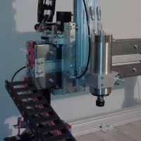
Here are some pictures from my build so far. I've got heat to my bed and head but haven't printed anything yet. Still trying to figure out the Repetier-Host settings.
- I had a little trouble getting the table top to fit and fractured the melamine a little.
- Added a little shrink tubing around the led for the bed.
- My soldering iron is from the mid 80s. The last computer I soldered with it was a TRS-80.
- But somehow I was able to successfully solder the LCD adapter. I kind-of ended up doing a wave soldering by hand and then painfully removed all the extra.
- Here is my build helper.
- I was worried at first that these crimp connectors might melt but so far they've held up.
- I found that a guitar pick is just the right width to fit in-between the column and the t-nut to help in screwing the belt clamps back on.
Re: David Smith's (Jetpad) Build
FYI, those crimping connectors were not a good idea. They eventually did start to melt a little and then uncrimped. I didn't have anything else handy so I end up using a household grounding wire crimps and then wrapped them in silicon tape.

Re: David Smith's (Jetpad) Build
@Jetpad - nice work so far! But did you run your belts properly? Looks like your belt enters the belt clamp from the top. It should be fed through the slot under the belt camp and through the hole in the middle of the belt clamp. The excess should hang out the top of the clamp.
(My apologies if you do have it correctly installed, but from the picture above, it doesn't look correct from that angle)
Here's a picture of my cheapskate, bit hard to see with the black on black, but you should get the idea.
http://www.flickr.com/photos/75376147@N ... 976583770/
(My apologies if you do have it correctly installed, but from the picture above, it doesn't look correct from that angle)
Here's a picture of my cheapskate, bit hard to see with the black on black, but you should get the idea.
http://www.flickr.com/photos/75376147@N ... 976583770/
(No trees were killed to post this message, but a large number of electrons were terribly inconvenienced.)
Re: David Smith's (Jetpad) Build
Thanks. Hmmm, it does look messed up in that picture. I must have discovered that belt problem not too long after I took the picture. I just checked my belts and I seem to have installed them correctly.
Re: David Smith's (Jetpad) Build
Here is a bracket that I came up with for lighting the build platform. I had some left over adhesive LED strips but they needed a smooth flat spot to mount them so I create this bracket that goes around the print head.
http://www.thingiverse.com/thing:76111
And here is my first version of it. My idea was to create a large smooth area to mount the LED so I created a ring that would hold a 9 led strip. Unfortunately I didn't think it through well enough.
After, I attached it to the printer and ran my first print job, I realized my problem.
It totally covered up the part when I was printing! But the light was bright.
And here is my first version of it. My idea was to create a large smooth area to mount the LED so I created a ring that would hold a 9 led strip. Unfortunately I didn't think it through well enough.
Re: David Smith's (Jetpad) Build
Here is my attempt at a part cooling fan for the Rostock Max.
http://www.thingiverse.com/thing:79471
A version using 25mm fans might work a little better and I'll probably try it as soon as I get ahold of some. If you want a challenging part to try printing (at least it was for me), the middle of the dome never quite came out right. It still seems to direct the air in the general direction of where I want it to go.
http://www.thingiverse.com/thing:79471
Re: David Smith's (Jetpad) Build
I got two pounds of the Taulman 618 Nylon. It came in two 1 lb rolls so I and decided to experiment with coloring one of the rolls. I had some left over Rit liquid dye in black and dark navy blue. I divided the roll into three parts and dyed one with the black, one with the navy blue and the other one I kind-of tie-dyed it half navy blue and kept the other half white. The picture doesn't really show the colors well. The black turned out like a very dark navy blue, the navy blue turned out nice dark purplish blue and the tie-dyed one has a range of white to dark purple in it.
To dye them, I put the filament in a quart ziplock bag, added one tablespoon of the dye, a splash of vinegar and probably about two cups of boiling water. I waited 45 minutes and then rinsed them in cold water.
I haven't tried to print with them yet. I'm having to print a reel right now so I'll have something to put them on.
I haven't tried to print with them yet. I'm having to print a reel right now so I'll have something to put them on.
Re: David Smith's (Jetpad) Build
Can you tell me where you got the LED strips? I'd like to add your illumination ring to my printer. Thanks.
Re: David Smith's (Jetpad) Build
This is the led strip that I ended up buying but I'd also seen a few on eBay.
http://amzn.com/B002QQ48TK
http://amzn.com/B002QQ48TK
Re: David Smith's (Jetpad) Build
Thanks. Did you just run straight to 12v on the PSU, or do you have it setup so you can turn them on/off via a switch?
Re: David Smith's (Jetpad) Build
I installed one of those circular push-to-kill switches next to the LCD panel and just use that to turn the printer on and off instead of the on/off switch that came with the kit. I mounted the kit's on/off switch in the hole to the left of the LCD that is labeled "light" and use that for the LED lights. But they stay on most of the time.
Re: David Smith's (Jetpad) Build
I discovered that I broke my extruder head. The (ceramic?) tube in the middle of it cracked and I suspect it was from one of the time the head was grinding into the platform.
When I went to put together my new extruder head, I decided not to use the RTV silicone this time. I just used silicone tape for everything and it came out great. One benefit is that you don't have to wait for it to cure and can put it straight into use. I even wrapped the resistors in a little bit of the silicone instead of using Aluminum foil. The tape seems to also deflect the 25mm fan's output away from the end of the head and onto the part that needs to be cooled. I should have taken pictures of it as I was putting it together but here is the final product.
When I went to put together my new extruder head, I decided not to use the RTV silicone this time. I just used silicone tape for everything and it came out great. One benefit is that you don't have to wait for it to cure and can put it straight into use. I even wrapped the resistors in a little bit of the silicone instead of using Aluminum foil. The tape seems to also deflect the 25mm fan's output away from the end of the head and onto the part that needs to be cooled. I should have taken pictures of it as I was putting it together but here is the final product.
Re: David Smith's (Jetpad) Build
I got the EZstruder today and installed it. I ended up putting it together 3 or 4 times trying to get the recessed holes in the melamine to lineup right but it doesn't look like it's possible. It runs very quietly compared to Steve's Extruder. Feeding in new filament is very easy and you don't really have to see into the hole to feed it correctly. Just stick it in the hole and it'll find it's way to the right spot. From the initial tests, it looks like I'm getting my best prints yet.
The updated EEProm "Extr.1 Steps per mm" setting that I came up with for it was 91.0 mm. I'd be interested in finding out what other's have found for that setting.
Yea! Now I'm now able to use retraction without worrying that the extruder would self destruct.
The updated EEProm "Extr.1 Steps per mm" setting that I came up with for it was 91.0 mm. I'd be interested in finding out what other's have found for that setting.
Yea! Now I'm now able to use retraction without worrying that the extruder would self destruct.
-
foshon

- Printmaster!
- Posts: 600
- Joined: Fri Mar 08, 2013 3:05 pm
- Location: Just to the right of SeeMeCNC
Re: David Smith's (Jetpad) Build
jetpad wrote:I got the EZstruder today and installed it. I ended up putting it together 3 or 4 times trying to get the recessed holes in the melamine to lineup right but it doesn't look like it's possible. It runs very quietly compared to Steve's Extruder. Feeding in new filament is very easy and you don't really have to see into the hole to feed it correctly. Just stick it in the hole and it'll find it's way to the right spot. From the initial tests, it looks like I'm getting my best prints yet.
The updated EEProm "Extr.1 Steps per mm" setting that I came up with for it was 91.0 mm. I'd be interested in finding out what other's have found for that setting.
Yea! Now I'm now able to use retraction without worrying that the extruder would self destruct.
Yay! We mounted it the same way!!
Edit: Got the exact s/mm.
Last edited by foshon on Sat May 11, 2013 7:33 pm, edited 1 time in total.
Purple = sarcasm
Please do a board search before posting your question, many have been answered with very time consuming detail already.
Please do a board search before posting your question, many have been answered with very time consuming detail already.
Re: David Smith's (Jetpad) Build
Is it possible to reuse the stepper motor from Steve's extruder in the EZstruder?
-
foshon
- Printmaster!
- Posts: 600
- Joined: Fri Mar 08, 2013 3:05 pm
- Location: Just to the right of SeeMeCNC
Re: David Smith's (Jetpad) Build
jesse wrote:Is it possible to reuse the stepper motor from Steve's extruder in the EZstruder?
Yeah, as long as you didn't have to alter the shaft in some way.
Purple = sarcasm
Please do a board search before posting your question, many have been answered with very time consuming detail already.
Please do a board search before posting your question, many have been answered with very time consuming detail already.

Re: David Smith's (Jetpad) Build
Does the EZstruder come with mounting bracket? And do you all feel this is the extruder to use, rather than the Steve's?
-"Simpler is better, except when complicated looks really cool."
-"As soon as you make something fool proof...along comes an idiot."
-"I have not failed. I've just found 10,000 ways that won't work." ~Thomas Edison
-"As soon as you make something fool proof...along comes an idiot."
-"I have not failed. I've just found 10,000 ways that won't work." ~Thomas Edison
Re: David Smith's (Jetpad) Build
It did come with a bracket printed in the black melamine. I reused the mounting screws and nuts from Steve's along with the stepper motor. It took a little effort to get the friction fit gear off the stepper motor. EZStruder is definitely much better than Steve's. But I do still seem to have a problem with the EZstruder at the moment. I'm printing in PLA and every-so-often it acts like it is slipping (maybe from the pressure of pushing the filament being to great?). There doesn't seem to be anything to adjust on it so I'm not sure how to fix the problem.
Re: David Smith's (Jetpad) Build
Well, I had an extra stepper motor (actually) three of them of the same model number from a Shapeoko kit that I haven't put together yet. I replaced the stepper with the Shapeoko motor and I'm no longer getting the slipping. So.... that also explains why I was getting "slipping" with Steve's Extruder for about a week that I couldn't get rid of no matter how much I tightened or adjusted things.
I took the bad stepper apart and this one doesn't seem to be the kind with any gears in it. I didn't see anything that looked obviously wrong with it and no grinded parts came out.
Edit: Unfortunately I'm still getting some occasional slipping with the new stepper motor. I guess they'd slip if there wasn't enough torque in some cases. Is that an EEProm setting I should change?
-
foshon
- Printmaster!
- Posts: 600
- Joined: Fri Mar 08, 2013 3:05 pm
- Location: Just to the right of SeeMeCNC
Re: David Smith's (Jetpad) Build
You could try to increase or decrease the digipot setting for the extruder motor. IIRC motors will slip/lose steps becuase there is not enough current going to them, or becuase the driver is getting hot and momentarily dropping out. Do you have heatsinks on your Rambo, or a fan blowing on it?jetpad wrote:Well, I had an extra stepper motor (actually) three of them of the same model number from a Shapeoko kit that I haven't put together yet. I replaced the stepper with the Shapeoko motor and I'm no longer getting the slipping. So.... that also explains why I was getting "slipping" with Steve's Extruder for about a week that I couldn't get rid of no matter how much I tightened or adjusted things.
I took the bad stepper apart and this one doesn't seem to be the kind with any gears in it. I didn't see anything that looked obviously wrong with it and no grinded parts came out.
Edit: Unfortunately I'm still getting some occasional slipping with the new stepper motor. I guess they'd slip if there wasn't enough torque in some cases. Is that an EEProm setting I should change?
Purple = sarcasm
Please do a board search before posting your question, many have been answered with very time consuming detail already.
Please do a board search before posting your question, many have been answered with very time consuming detail already.
Re: David Smith's (Jetpad) Build
No, I don't have heat sinks or a fan blowing on the board. Does it matter if the actual stepper motor gets hot? Would it ever need a heat sink?
Edit: I ordered some heat sinks and stuck a fan in the case blowing on the Rambo board and the "slipping" has disappeared! I haven't touched the Digipot settings.
Edit: I ordered some heat sinks and stuck a fan in the case blowing on the Rambo board and the "slipping" has disappeared! I haven't touched the Digipot settings.
-
foshon
- Printmaster!
- Posts: 600
- Joined: Fri Mar 08, 2013 3:05 pm
- Location: Just to the right of SeeMeCNC
Re: David Smith's (Jetpad) Build
jetpad wrote:No, I don't have heat sinks or a fan blowing on the board. Does it matter if the actual stepper motor gets hot? Would it ever need a heat sink?
Edit: I ordered some heat sinks and stuck a fan in the case blowing on the Rambo board and the "slipping" has disappeared! I haven't touched the Digipot settings.
Yeah, heat destroys most things electronic eventually. In the case of motors, I believe it leads to premature failure of the windings. Possibly the varnish coating the wires, just a guess. There are several nema 17 fan mounts available on thingiverse.
Personal experience tells me they have to get awfully hot before things go south with any speed. I had a motor on my MM that got so hot after a 7 hour print I couldn't touch it for long. I discovered that my pot (physical) was turned up. I also realized that I never really tuned any of them. That motor is still chugging along just fine.
Purple = sarcasm
Please do a board search before posting your question, many have been answered with very time consuming detail already.
Please do a board search before posting your question, many have been answered with very time consuming detail already.
-
Polygonhell
- ULTIMATE 3D JEDI
- Posts: 2417
- Joined: Mon Mar 26, 2012 1:44 pm
- Location: Redmond WA
Re: David Smith's (Jetpad) Build
Most Nema 17 motors are rated for continuous operation at 80C, I'd bet yours is much less than that, my direct drive extruder motor runs around 50C.
Printer blog http://3dprinterhell.blogspot.com/