Aurora's Rostock Max v2 build
Re: Aurora's Rostock Max v2 build
Shoulda got that creepy guy to tap it for you!! 
*not actually a robot
Re: Aurora's Rostock Max v2 build
Yeah it was too late to ask him. I would have done that had I known the part never shipped...bot wrote:Shoulda got that creepy guy to tap it for you!!
-
RAMTechRob
- Printmaster!
- Posts: 171
- Joined: Tue Apr 22, 2014 10:00 pm
Re: Aurora's Rostock Max v2 build
Ace Hardware or Home Depot have taps and handles that can get you fixed up tonight. About $4.00 for a tap and you can even use an adjustable wrench for a handle.
-
RAMTechRob
- Printmaster!
- Posts: 171
- Joined: Tue Apr 22, 2014 10:00 pm
Re: Aurora's Rostock Max v2 build
If you are close to Bablylon, shoot me PM. I have a friend there that can do it.
Re: Aurora's Rostock Max v2 build
Really? I thought you'd need like a drill press and a vice or something to make sure its straight... I've never tapped anything lol. There's a home depot and an ace like 1 mile from me (actually I used to work at ace lol and I didn't even know they had them)RAMTechRob wrote:Ace Hardware or Home Depot have taps and handles that can get you fixed up tonight. About $4.00 for a tap and you can even use an adjustable wrench for a handle.
Re: Aurora's Rostock Max v2 build
Babylon is about 30 minutes from me... but if its easy enough to do on my own I would just buy the toolRAMTechRob wrote:If you are close to Bablylon, shoot me PM. I have a friend there that can do it.
-
RAMTechRob
- Printmaster!
- Posts: 171
- Joined: Tue Apr 22, 2014 10:00 pm
Re: Aurora's Rostock Max v2 build
[img]http://upload.wikimedia.org/wikipedia/c ... wrench.jpg[/img]
its very easy. The hardest part will be to figure out what size thread it is. You just need to use a screw and see what size fits. Unless one of the SeeMeCNC people know off the top of thier heads?
its very easy. The hardest part will be to figure out what size thread it is. You just need to use a screw and see what size fits. Unless one of the SeeMeCNC people know off the top of thier heads?
Re: Aurora's Rostock Max v2 build
That is one HUGE picture... but yes it is very easy. The hole lines everything up for you... you just need to turn it. It's all done by hand/in hand. You don't NEED a vice, but it would help. Safety gloves/garden gloves to protect your hand if holding the piece.
*not actually a robot
-
RAMTechRob
- Printmaster!
- Posts: 171
- Joined: Tue Apr 22, 2014 10:00 pm
Re: Aurora's Rostock Max v2 build
Sorry, i'm on my phone in the airport. I'm sure Youtube has a video about tapping a hole.
Re: Aurora's Rostock Max v2 build
Hey guys... guess what I just did!
I'll give you a hint...
[img]http://staticexperiment.com/rostock/DSCN0210s.jpg[/img][img]http://staticexperiment.com/rostock/DSCN0209s.jpg[/img]
You have no idea how happy I am that this worked and was so easy. I had no idea it was that simple. I couldn't find an exact match for the existing set screws so I picked out a 4-40 tap since it was the closest in width and bought 2 matching 4-40 screws. Once screwed all the way in they stick out a tiny bit, but they shouldn't be in the way of anything.
Thanks everyone for your help with this, I really appreciate it. I just mounted it and ran the drive belt up that tower and finished mounting the effector arms. Pictures and details to follow in my next post (I just have to prepare the images and upload them)
Re: Aurora's Rostock Max v2 build
So when I last left off with my official build progress posts, I was up to mounting the top. I had the top built in that last thread, now its time to mount it. It was a bit tricky to get all lined up, but it went on fairly easy.
[img]http://staticexperiment.com/rostock/DSCN0180s.jpg[/img]
I pulled the wires through and mounted the idlers, no problem.
[img]http://staticexperiment.com/rostock/DSCN0181s.jpg[/img]
Next came the drive belts. They were a bit annoying, but with the right tools its easy. Routing the belt through the idlers and pulley wasn't too bad, I just shoved it through until i found a piece I could grab, and then pushed it around the pulley and then out around the idler. Pulling the belt through to the front of the cheapskate was a bit tricky. What I ended up doing was placing needle nose pliers into the slot in the cheapskate and then fed the belt towards it. I was then able to grab the end of the belt with the pliers and pull it through. In retrospect I should have used my forceps since they're smaller and a bit more nimble.
[img]http://staticexperiment.com/rostock/DSCN0184s.jpg[/img]
(And yes, I forgot to pull of the mask on the melamine... its gone now, don't worry lol)
For anyone wondering how I held up the cheapskates while working on them, this is what I did:
[img]http://staticexperiment.com/rostock/DSCN0188s.jpg[/img]
At the time I only had 2 of the pulleys, so I moved on to the ezstruder. Assembly was fairly straight forward, though I accidentally mounted the hobbed gear upsidedown initially. I quickly realized that was wrong and fixed it. Here we have the fully assembled ezstruder on its mount:
[img]http://staticexperiment.com/rostock/DSCN0192s.jpg[/img]
Mounting the ezstruder was simple, nothing much to say about it...
[img]http://staticexperiment.com/rostock/DSCN0196s.jpg[/img]
I decided not to get quick disconnects for the extruder motor. It's not something that's going to be changed out often and if it does fail, there's about a mile of extra wire, it can easily be cut out and replaced. In order to save myself later on, I left as much extra on the motor as possible and bundled it up and tied it behind the ezstruder mount. I will also leave some extra wire at the base of the tower so I can always feed more up if I need to.
Helping hands are the best thing ever. I don't know what I'd do without this thing:
[img]http://staticexperiment.com/rostock/DSCN0198s.jpg[/img]
After wiring the motor up, I loomed the hot end wires and cleaned everything up on top. I love nice neat wiring. There's nothing more satisfying.
[img]http://staticexperiment.com/rostock/DSCN0199s.jpg[/img]
You can also see the lonely Y axis carriage sitting at the bottom... wishing it could join its buddies above.
And a nice shot of the loomed wire from below:
[img]http://staticexperiment.com/rostock/DSCN0200s.jpg[/img]
Next up comes the hot end. This was a little difficult and I wish I had left a couple more inches of wire to work with, but I was able to push the loom back a bit to make it easier to solder. There was something very satisfying about the way the instructions say to bend the resistor leads... I think it looks cool, lol. Here's the finished hot end, with the thermistor secured to the heater lead:
[img]http://staticexperiment.com/rostock/DSCN0201s.jpg[/img]
On a side note, I wish the instructions said to take off the nut on the hot end BEFORE soldering the wires to it. It was difficult to remove, required a lot of force and I was very worried about ruining the wires I just crimped. Also, in regard to the crimp... I thought I was going to be able to get a hold of JST connectors locally, but I couldn't... So I decided that will just have to be an upgrade later on if I ever want to change out the hot end. I don't foresee wanting to do that right now, so this is fine.
Here's the hot end on its mount:
[img]http://staticexperiment.com/rostock/DSCN0204s.jpg[/img]
Another note about the manual in regards to the hot end... The instructions say theres TWO spacers for the mount, but there's only supposed to be one. Once again I went nuts and panicked thinking I lost a piece only to scroll down further and realize this was a typo. So just so you all know, there's only one spacer.
The effector plate was a major pain in the ass. I don't know if mine wasn't made properly or something, but it was exceedingly difficult to get the axles onto it. I had to use my pliers to pull apart the pieces the axle slides into. What I did was put one side of the pliers against one piece, and the other side against the next piece and twisted the pliers in order to slightly pull them apart enough to fit the axle through. I did this for each pair until the axle was through. I then fine tuned the position of the axle by pressing it against the flat side of the pliers near the joint. It worked well and I was able to get the axles perfectly centered:
[img]http://staticexperiment.com/rostock/DSCN0207s.jpg[/img]
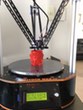
And finally, for now, here's the effector plate and arms mounted. As you can see, while I was waiting for the pulley I went ahead and took care of some other mundane things like the filament spool holder and the plates that enclose the top. When I found out that the replacement pulley wasn't going to get here for another few days I ended up going out and buying a tap to fix the pulley myself, as I mentioned in my previous post.
[img]http://staticexperiment.com/rostock/DSCN0215s.jpg[/img]
Tonight I have my friend's birthday to go to tonight so I won't be working on it much today... I will hopefully be working on it tomorrow though.
[img]http://staticexperiment.com/rostock/DSCN0180s.jpg[/img]
I pulled the wires through and mounted the idlers, no problem.
[img]http://staticexperiment.com/rostock/DSCN0181s.jpg[/img]
Next came the drive belts. They were a bit annoying, but with the right tools its easy. Routing the belt through the idlers and pulley wasn't too bad, I just shoved it through until i found a piece I could grab, and then pushed it around the pulley and then out around the idler. Pulling the belt through to the front of the cheapskate was a bit tricky. What I ended up doing was placing needle nose pliers into the slot in the cheapskate and then fed the belt towards it. I was then able to grab the end of the belt with the pliers and pull it through. In retrospect I should have used my forceps since they're smaller and a bit more nimble.
[img]http://staticexperiment.com/rostock/DSCN0184s.jpg[/img]
(And yes, I forgot to pull of the mask on the melamine... its gone now, don't worry lol)
For anyone wondering how I held up the cheapskates while working on them, this is what I did:
[img]http://staticexperiment.com/rostock/DSCN0188s.jpg[/img]
At the time I only had 2 of the pulleys, so I moved on to the ezstruder. Assembly was fairly straight forward, though I accidentally mounted the hobbed gear upsidedown initially. I quickly realized that was wrong and fixed it. Here we have the fully assembled ezstruder on its mount:
[img]http://staticexperiment.com/rostock/DSCN0192s.jpg[/img]
Mounting the ezstruder was simple, nothing much to say about it...
[img]http://staticexperiment.com/rostock/DSCN0196s.jpg[/img]
I decided not to get quick disconnects for the extruder motor. It's not something that's going to be changed out often and if it does fail, there's about a mile of extra wire, it can easily be cut out and replaced. In order to save myself later on, I left as much extra on the motor as possible and bundled it up and tied it behind the ezstruder mount. I will also leave some extra wire at the base of the tower so I can always feed more up if I need to.
Helping hands are the best thing ever. I don't know what I'd do without this thing:
[img]http://staticexperiment.com/rostock/DSCN0198s.jpg[/img]
After wiring the motor up, I loomed the hot end wires and cleaned everything up on top. I love nice neat wiring. There's nothing more satisfying.
[img]http://staticexperiment.com/rostock/DSCN0199s.jpg[/img]
You can also see the lonely Y axis carriage sitting at the bottom... wishing it could join its buddies above.
And a nice shot of the loomed wire from below:
[img]http://staticexperiment.com/rostock/DSCN0200s.jpg[/img]
Next up comes the hot end. This was a little difficult and I wish I had left a couple more inches of wire to work with, but I was able to push the loom back a bit to make it easier to solder. There was something very satisfying about the way the instructions say to bend the resistor leads... I think it looks cool, lol. Here's the finished hot end, with the thermistor secured to the heater lead:
[img]http://staticexperiment.com/rostock/DSCN0201s.jpg[/img]
On a side note, I wish the instructions said to take off the nut on the hot end BEFORE soldering the wires to it. It was difficult to remove, required a lot of force and I was very worried about ruining the wires I just crimped. Also, in regard to the crimp... I thought I was going to be able to get a hold of JST connectors locally, but I couldn't... So I decided that will just have to be an upgrade later on if I ever want to change out the hot end. I don't foresee wanting to do that right now, so this is fine.
Here's the hot end on its mount:
[img]http://staticexperiment.com/rostock/DSCN0204s.jpg[/img]
Another note about the manual in regards to the hot end... The instructions say theres TWO spacers for the mount, but there's only supposed to be one. Once again I went nuts and panicked thinking I lost a piece only to scroll down further and realize this was a typo. So just so you all know, there's only one spacer.
The effector plate was a major pain in the ass. I don't know if mine wasn't made properly or something, but it was exceedingly difficult to get the axles onto it. I had to use my pliers to pull apart the pieces the axle slides into. What I did was put one side of the pliers against one piece, and the other side against the next piece and twisted the pliers in order to slightly pull them apart enough to fit the axle through. I did this for each pair until the axle was through. I then fine tuned the position of the axle by pressing it against the flat side of the pliers near the joint. It worked well and I was able to get the axles perfectly centered:
[img]http://staticexperiment.com/rostock/DSCN0207s.jpg[/img]
And finally, for now, here's the effector plate and arms mounted. As you can see, while I was waiting for the pulley I went ahead and took care of some other mundane things like the filament spool holder and the plates that enclose the top. When I found out that the replacement pulley wasn't going to get here for another few days I ended up going out and buying a tap to fix the pulley myself, as I mentioned in my previous post.
[img]http://staticexperiment.com/rostock/DSCN0215s.jpg[/img]
Tonight I have my friend's birthday to go to tonight so I won't be working on it much today... I will hopefully be working on it tomorrow though.
Re: Aurora's Rostock Max v2 build
Congrats on your new Tap Fu! 
If you think those little metal helping hands are neat, then you'll really get a charge out of this: http://eleccelerator.com/improved-third ... lant-hose/
You can get the cooling hose off of eBay - I got a pack of 11 for $12. If memory serves, the use a 1/2" NPT tap, but you should check once the new ones arrive. Instead of going the whole diy route like the builder did, I scavenged the parts required from my old helping-hand. Worked out fantastic.
g.
Delta Power!
Defeat the Cartesian Agenda!
http://www.f15sim.com - 80-0007, The only one of its kind.
http://geneb.simpits.org - Technical and Simulator Projects
Defeat the Cartesian Agenda!
http://www.f15sim.com - 80-0007, The only one of its kind.
http://geneb.simpits.org - Technical and Simulator Projects
-
Eaglezsoar

- ULTIMATE 3D JEDI
- Posts: 7159
- Joined: Sun Apr 01, 2012 5:26 pm
Re: Aurora's Rostock Max v2 build
Aurora900, a very nice build with a lot of pictures.
Congrats on getting that pulley tapped and thanks again
for all of the pictures.
Congrats on getting that pulley tapped and thanks again
for all of the pictures.
Re: Aurora's Rostock Max v2 build
Lookin' good now...
Got the better of you and you went and got a tap and handle....
Got the better of you
Bob
Rostock Max V2, Ball Cup Arms, New Carriages, HE280, Dampers, PSU Breathing, Simplify 3D, GeckoTek3D, Raspberry Pi3. Duet soon... Kossel Mini still under construction.
Delta's are the way!
Rostock Max V2, Ball Cup Arms, New Carriages, HE280, Dampers, PSU Breathing, Simplify 3D, GeckoTek3D, Raspberry Pi3. Duet soon... Kossel Mini still under construction.
Delta's are the way!
Re: Aurora's Rostock Max v2 build
What can I say... I'm not a very patient girl...crocky wrote:Lookin' good now...
Got the better of you
I really wanted to have it done this weekend. And I thought I'd clock in at well under 20 hours but I think im coming closer to 20 than I thought
-
RAMTechRob
- Printmaster!
- Posts: 171
- Joined: Tue Apr 22, 2014 10:00 pm
Re: Aurora's Rostock Max v2 build
Looking good. I would never have waited either.
Re: Aurora's Rostock Max v2 build
Alright... now I'm really stuck. I'm up to wiring the rambo board and putting the connectors on the various wires that have to plug into it. I can't get the little female pins on the 18ga wire. It's just way too big... the picture in the manual shows the wire being completely surrounded after it was crimped but mine just seems nowhere near big enough to fit around that wire. Only about half the strands of the wire seem to actually fit into the pin... I don't know what I'm doing wrong here
Re: Aurora's Rostock Max v2 build
Can you take a picture of the pin vs the wire? Do you have other crimp pins?
*not actually a robot
Re: Aurora's Rostock Max v2 build
I can take a picture tomorrow... It's what came with the rambo kit, they're all the same (I mean, the ones in the bag are all the same)bot wrote:Can you take a picture of the pin vs the wire? Do you have other crimp pins?
-
Earthbound
- Printmaster!
- Posts: 458
- Joined: Sun Sep 07, 2014 2:39 am
Re: Aurora's Rostock Max v2 build
I gave up on trying to achieve a decent crimp and just soldered the pins onto the wires.Aurora900 wrote:Alright... now I'm really stuck. I'm up to wiring the rambo board and putting the connectors on the various wires that have to plug into it. I can't get the little female pins on the 18ga wire. It's just way too big... the picture in the manual shows the wire being completely surrounded after it was crimped but mine just seems nowhere near big enough to fit around that wire. Only about half the strands of the wire seem to actually fit into the pin... I don't know what I'm doing wrong here
"Trust no quote from the Internet." - Abraham Lincoln
Re: Aurora's Rostock Max v2 build
I was considering that actually... but I didn't want to solder at 2amEarthbound wrote:I gave up on trying to achieve a decent crimp and just soldered the pins onto the wires.Aurora900 wrote:Alright... now I'm really stuck. I'm up to wiring the rambo board and putting the connectors on the various wires that have to plug into it. I can't get the little female pins on the 18ga wire. It's just way too big... the picture in the manual shows the wire being completely surrounded after it was crimped but mine just seems nowhere near big enough to fit around that wire. Only about half the strands of the wire seem to actually fit into the pin... I don't know what I'm doing wrong here
-
Earthbound
- Printmaster!
- Posts: 458
- Joined: Sun Sep 07, 2014 2:39 am
Re: Aurora's Rostock Max v2 build
The pins are really not big enough for #18, or at least #18 that is so coarsely stranded.
"Trust no quote from the Internet." - Abraham Lincoln
-
Earthbound
- Printmaster!
- Posts: 458
- Joined: Sun Sep 07, 2014 2:39 am
Re: Aurora's Rostock Max v2 build
Once you've got the pins on the white and green wires, you'll find that getting them into the connector housing is not much fun either.
"Trust no quote from the Internet." - Abraham Lincoln
Re: Aurora's Rostock Max v2 build
Solder is also good. It is what i did.
EXCEPT the hotend resistance wires!
EXCEPT the hotend resistance wires!
When on mobile I am brief and may be perceived as an arsl.
Re: Aurora's Rostock Max v2 build
Why do you say except those? Those are specifically the ones I can't get into the pin....teoman wrote:Solder is also good. It is what i did.
EXCEPT the hotend resistance wires!