Mhackney's Rostock Max

Re: Mhackney's Rostock Max
@flateric - the "man" on home brew tool changes is Hoss over at the CNC forum. I'm building his ATC 4 and the power draw bar based on his design. Check it out and read his posts on CNCZone. I can point you if you can't find it but he's a fixture on the zone!
Sublime Layers - my blog on Musings and Experiments in 3D Printing Technology and Art
Start Here:
A Strategy for Successful (and Great) Prints
Strategies for Resolving Print Artifacts
The Eclectic Angler
Re: Mhackney's Rostock Max
The thought of an ATC makes me drool. Then I see the $12k price tag for it (for my ShopBot), sob quite a bit and move on. 
g.
g.
Delta Power!
Defeat the Cartesian Agenda!
http://www.f15sim.com - 80-0007, The only one of its kind.
http://geneb.simpits.org - Technical and Simulator Projects
Defeat the Cartesian Agenda!
http://www.f15sim.com - 80-0007, The only one of its kind.
http://geneb.simpits.org - Technical and Simulator Projects
Re: Mhackney's Rostock Max
That's one advantage of building your own. Of course a ShopBot is a different beast. The ATC and power draw bar will cost me about $300 for parts. Since Hoss has done the hard work of designing the stuff, there won't be a lot of wasted time in building trial and error!
Sublime Layers - my blog on Musings and Experiments in 3D Printing Technology and Art
Start Here:
A Strategy for Successful (and Great) Prints
Strategies for Resolving Print Artifacts
The Eclectic Angler
A nice little prop!
Bob Warfield over at CNC Cookbook writes a really nice blog. His post this morning is called Manufacturing is Cool Again: It's about time. Most of it focuses on 3D printing technology used in manufacturing but the last company he mentions is my company, The Eclectic Angler, and the work I do using my home-brewed CNC equipment to manufacture reels and reel kits. Kinda cool!
Sublime Layers - my blog on Musings and Experiments in 3D Printing Technology and Art
Start Here:
A Strategy for Successful (and Great) Prints
Strategies for Resolving Print Artifacts
The Eclectic Angler
-
Eaglezsoar

- ULTIMATE 3D JEDI
- Posts: 7159
- Joined: Sun Apr 01, 2012 5:26 pm
Re: A nice little prop!
Yep, kinda cool. Don't get a big head! Seriously, I'd be on cloud 9 for the recognition.mhackney wrote:Bob Warfield over at CNC Cookbook writes a really nice blog. His post this morning is called Manufacturing is Cool Again: It's about time. Most of it focuses on 3D printing technology used in manufacturing but the last company he mentions is my company, The Eclectic Angler, and the work I do using my home-brewed CNC equipment to manufacture reels and reel kits. Kinda cool!
Carl
Re: Mhackney's Rostock Max
That's awesome Mhackney, congrats! And I like your shop. Wish I had me one of those.

Re: Mhackney's Rostock Max
Michael, do you have any pictures you'd care to post of the mounting for your power supply and associated wiring?
- dan
- dan
Simple Calibration preamble
I moved a copy of this from another post I made so I have everything in one place. I am working on a calibration guide for geneb's manual but here is a quick overview of the process from the top of my head:
I am not sure if there is a least painful method to get good prints! That is the Holy Grail of filament extrusion printers. The RepRap forums are filled with posts about it. The most workable and least painful approach seems to be a systematic "bottoms up" system. Once you have the basic mechanical and electrical demons excised THEN you start on print calibration:
1) extruder adjustment to get the filament moving - in both directions - with enough force to extrude and not slip but not so much so as to distort the filament. This assumes some reasonable setting for hot end temperature. I always start with 225°C for ABS and 180°C for PLA but I am talking actual temperature measured with a thermocouple at the nozzle/heat block junction. Once I know what the delta is I use that offset as a fudge factor for temperature settings in my slicer and host. Advanced Note: I also check the temperature by inserting the thermocouple into the hot end all the way (without filament of course) and ramp the temp up in my host and watch the thermocouple. I have a spreadsheet with the offsets for my Rostock. The next step is to adjust the thermistor table to tune it to my setup but I have not done that yet.
2) print the single wall cube object to work out the bugs in extrusion, filament starving, etc. Don't worry about globing or threads until the basic extrusion calibration and that it is working properly. You also need to measure your filament diameter to use in the slicer and work out other parameters. I also fine tune the temperature to get best results for the specific filament this way (each roll is different) as I posted somewhere else.
3) then work on infill with my "Z calibration thing". This actually attacks two areas; it makes sure the mechanical delta arm assembly has good free movement and it allows you to work on the settings to get the best infill without over- or under- fill.
4) once you have the basics above dialed in, then you move on to eliminating blobbing and stringing. These can be greatly affected by the items above and fall into the camp of the overall "systems" tuning whereas the first 3 items focus on individual parameter tuning.
Then, you go to sleep, wake up the next day and nothing works! The humidity has gone up, it's a full moon, whatever. It is through previous experience that you'll recognize the issue and know how to compensate.
regards,
Michael
Sublime Layers - my blog on Musings and Experiments in 3D Printing Technology and Art
Start Here:
A Strategy for Successful (and Great) Prints
Strategies for Resolving Print Artifacts
The Eclectic Angler
-
Eaglezsoar
- ULTIMATE 3D JEDI
- Posts: 7159
- Joined: Sun Apr 01, 2012 5:26 pm
Re: Mhackney's Rostock Max
Do you mean after doing all this hard, incredibly time consuming tweaking, the whole thing is worthless if there is a full moon the next day?
Oh woe is me! I am going to buy an old erector set and build things like I did when I was young. This 3D stuff is too hard!
Oh woe is me! I am going to buy an old erector set and build things like I did when I was young. This 3D stuff is too hard!
Re: Mhackney's Rostock Max
I was kidding (sort of)!
Sublime Layers - my blog on Musings and Experiments in 3D Printing Technology and Art
Start Here:
A Strategy for Successful (and Great) Prints
Strategies for Resolving Print Artifacts
The Eclectic Angler
Re: Mhackney's Rostock Max
Hi mhackney,
what for PID-values do you have for the heatbed with aluminium plate and glass?
I think my autotune-values
Kp: 901.88
Ki: 400.66
Kd: 507.53
are fare away from good...
what for PID-values do you have for the heatbed with aluminium plate and glass?
I think my autotune-values
Kp: 901.88
Ki: 400.66
Kd: 507.53
are fare away from good...
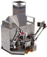
3rd party Power Supply Mount
@dbarrans - here is a quick photo of how my power supply is mounted:
[img]http://mhackney.zenfolio.com/img/s8/v79 ... 0908-3.jpg[/img]
It basically "rests" in the spot where the PC power supply that comes with the Rostock MAX mounted. I made a wood mount block 3" wide, 4" long and 1" thick that screws to the bottom (actually side) of the supply and is then screwed on to the Rostock base with two wood screws through the bottom. I can't move my machine around without clearing off my desk to get to the other side!
There are 3 sets of terminals, I have wires (+ and -) from each set, that run to the 3 sets of terminals on RAMBo. The 22 gauge red and black wires you see go to my LEDs and fan. I intend to mount a switch for the AC line coming in. Right now it is on a power strip with a switch.
Sublime Layers - my blog on Musings and Experiments in 3D Printing Technology and Art
Start Here:
A Strategy for Successful (and Great) Prints
Strategies for Resolving Print Artifacts
The Eclectic Angler
Re: Mhackney's Rostock Max
@aehM_Key - my values won't work and probably not be in the ball park since I am using the 12V 30 amp supply. However they are:
Code: Select all
*/
/** P-gain.  Overridden if EEPROM activated. */
#define HEATED_BED_PID_PGAIN   184.00
/** I-gain  Overridden if EEPROM activated.*/
#define HEATED_BED_PID_IGAIN   63.45
/** Dgain.  Overridden if EEPROM activated.*/
#define HEATED_BED_PID_DGAIN 133.40
5
Sublime Layers - my blog on Musings and Experiments in 3D Printing Technology and Art
Start Here:
A Strategy for Successful (and Great) Prints
Strategies for Resolving Print Artifacts
The Eclectic Angler
Re: Mhackney's Rostock Max
Thanks. I know, just as a reference. I have ~300W for the Heatbed now.
Onyx Spacer Mod
I take my Onyx on and off a lot to test things like the Aluminum Heat Dissipator plates I manufacture. I finally got tired of struggling with poking the power connection wires around to make sure the Onyx sits flat and the wires are not strained. So, I simply cut the snowflake spacer to make the necessary clearance. I am going to talk to Steve & John about making this mod on the laser cut part in the kit, but for now you can do your own. Simply extend the line from the original cutout down. I've included Empirical (1-7/8") and metric (4.75cm) measurements on the photo. I used a band saw but a hacksaw or even drilling a series of 1/8" holes and knocking the piece out will work fine.
[img]http://mhackney.zenfolio.com/img/s8/v84 ... 0704-3.jpg[/img]
It works great and I don't have any undue strain on my wiring now.
[img]http://mhackney.zenfolio.com/img/s8/v84 ... 0704-3.jpg[/img]
It works great and I don't have any undue strain on my wiring now.
Sublime Layers - my blog on Musings and Experiments in 3D Printing Technology and Art
Start Here:
A Strategy for Successful (and Great) Prints
Strategies for Resolving Print Artifacts
The Eclectic Angler
Re: Mhackney's Rostock Max
I thought about doing that, but I chiseled the wiring slot instead to allow the wires to go though at an angle. I didn't want to lose any of the stiffness the snowflake provides for the Onyx.
- dan
- dan
Re: Mhackney's Rostock Max
Just wanted to post a link to all of my Rostock Max photos. 153 and counting!
Sublime Layers - my blog on Musings and Experiments in 3D Printing Technology and Art
Start Here:
A Strategy for Successful (and Great) Prints
Strategies for Resolving Print Artifacts
The Eclectic Angler
Add-A-Struder
Wish me luck as I forge down the path of dual extruders! My Add-A-Struder kit arrived today:
[img]http://mhackney.zenfolio.com/img/s8/v75 ... 2606-3.jpg[/img]
Everything should look familiar to a Rostock owner/builder.
I am going to install Av8r RC's spool width extension print to this as I build it.
regards,
Michael
[img]http://mhackney.zenfolio.com/img/s8/v75 ... 2606-3.jpg[/img]
Everything should look familiar to a Rostock owner/builder.
I am going to install Av8r RC's spool width extension print to this as I build it.
regards,
Michael
Sublime Layers - my blog on Musings and Experiments in 3D Printing Technology and Art
Start Here:
A Strategy for Successful (and Great) Prints
Strategies for Resolving Print Artifacts
The Eclectic Angler
Add-A-Struder
Ahhhh, how I missed the fragrance of laser cut melamine! One nice thing, the parts are not taped together in a sheet! The laser cut parts are wrapped in plastic. Just peal the protective film and assemble. I checked all of the parts and they are nicely cut. It is important for folks to realize that laser cut parts may have a slight bevel to the cut. My parts are quite nice compared to many other laser cut products I've seen. I get a fair amount of water jet parts cut and it also exhibits this effect. Basically, the point where the laser (or water jet) enters the top of the part is narrower than where it exits. The cut is actually a section of a cone. The thicker and denser the stock, the more pronounced the effect.
Sublime Layers - my blog on Musings and Experiments in 3D Printing Technology and Art
Start Here:
A Strategy for Successful (and Great) Prints
Strategies for Resolving Print Artifacts
The Eclectic Angler
Re: Mhackney's Rostock Max
Are you building something to hold both hot ends or is there a mount in the kit?
Re: Mhackney's Rostock Max
I am building a quick change tool mount that I plan to offer along with some other tool options. I will have a single and double hotend holder. Their was no double holder in the kit. The holder that came stock has 3 holes but the way they are arranged along with the support assembly, you can't just drop a 2nd hot end in place. But be patient, their may be a simple way around that!
Sublime Layers - my blog on Musings and Experiments in 3D Printing Technology and Art
Start Here:
A Strategy for Successful (and Great) Prints
Strategies for Resolving Print Artifacts
The Eclectic Angler
-
MorbidSlowBurn

- Printmaster!
- Posts: 169
- Joined: Sun Mar 03, 2013 5:33 pm
Re: Mhackney's Rostock Max
I can't wait to see your dual extruder solution. Are you going to make it adjustable to allow each extruder height to be "zeroed". I know my build platform is not perfectly parrallel to the extruder platform.
Re: Mhackney's Rostock Max
Yes, that is a big reason to do my own actually.
Sublime Layers - my blog on Musings and Experiments in 3D Printing Technology and Art
Start Here:
A Strategy for Successful (and Great) Prints
Strategies for Resolving Print Artifacts
The Eclectic Angler
Re: Mhackney's Rostock Max
Do you think stringing and ooze will be a big problem with dual setup? Been using the suck wipe and prime in kiss pro does a pretty good job, I still have yet to perfect it.
Just noticed 28 pages. It's turning into hoss's page on cnc zone. And we have a lot less members I'm sure. I like it.
Just noticed 28 pages. It's turning into hoss's page on cnc zone. And we have a lot less members I'm sure. I like it.
-
MorbidSlowBurn
- Printmaster!
- Posts: 169
- Joined: Sun Mar 03, 2013 5:33 pm
Re: Mhackney's Rostock Max
Mhackney- what are you planning to do with the dual extruders? Are you planning one to be support? Or are you attempting dual structure material such as two colors or even abs with transparent PLA window? What slicing program do you think will accommodate all these options?