I would have paid extra to get bubble wrap instead.
dmlonestar - Rostock build
-
dmlonestar
- Plasticator
- Posts: 9
- Joined: Fri Mar 01, 2013 8:42 pm
dmlonestar - Rostock build
And so it begins...
Peanuts..[20 minute interlude to collect static-charged peanuts and bag them].
I would have paid extra to get bubble wrap instead.
Peanuts..[20 minute interlude to collect static-charged peanuts and bag them].
I would have paid extra to get bubble wrap instead.
-
dmlonestar
- Plasticator
- Posts: 9
- Joined: Fri Mar 01, 2013 8:42 pm
Re: dmlonestar - Rostock build
Items floating in the larger box (minus the 3 spools of ABS - maybe should have shipped those separate):
Smaller box (electronics, motors, arms, etc):
Larger box (add-a-struder + motor, LCD, Onyx, pen-holder):
Re: dmlonestar - Rostock build
ahhh rostock porn.
My rostock build log http://forum.seemecnc.com/viewtopic.php?f=42&t=1228
-
dmlonestar
- Plasticator
- Posts: 9
- Joined: Fri Mar 01, 2013 8:42 pm
Re: dmlonestar - Rostock build
Step 1 of the assembly.. "oh no.. what's this?"
Closer look:
A disappointing find. But on the plus side, there's only a ridge on one side so the crack doesn't go all the way through. And it's on the base, so I don't think it would be visible. Maybe I'll just add some plastics weld to make sure it doesn't spread.
Now about that decision to pack 3 spools of ABS on top of things...
The short of it is, looks like I'll need to review all the pieces sooner-rather-than-later to make sure that's the extent of it.
Now about that decision to pack 3 spools of ABS on top of things...
The short of it is, looks like I'll need to review all the pieces sooner-rather-than-later to make sure that's the extent of it.
-
MorbidSlowBurn

- Printmaster!
- Posts: 169
- Joined: Sun Mar 03, 2013 5:33 pm
Re: dmlonestar - Rostock build
dmlonestar, welcome to the forum.
I am fairly new here also. Looks like you have the acrylic version. I do reccomend when you start building, before removing the backing paper, to use a countersink bit and hit the rings that Geneb says to pop out with a knife. Just stop drilling when the countersink hits the ring. I did each piece as I was assembling. The first piece I took the backing paper off before countersinking and the shavings stuck to the piece. After that I left the paper on and had no problems cleaning the pieces.
I am fairly new here also. Looks like you have the acrylic version. I do reccomend when you start building, before removing the backing paper, to use a countersink bit and hit the rings that Geneb says to pop out with a knife. Just stop drilling when the countersink hits the ring. I did each piece as I was assembling. The first piece I took the backing paper off before countersinking and the shavings stuck to the piece. After that I left the paper on and had no problems cleaning the pieces.
-
MorbidSlowBurn
- Printmaster!
- Posts: 169
- Joined: Sun Mar 03, 2013 5:33 pm
Re: dmlonestar - Rostock build
Wow, sorry to see the crack. You posted as I was typing my message. I know I have a spot where I over tightened and have a crack. I have some acrylic glue that I bought from a local plastic supply place. It was about $7 and he even through in an applicator. If you can get your hands on that it will actually melt the acrylic together. But I will say if you let SeeMeCNC know they will help. I had a couple of missing screws and they sent them right out.
-
dmlonestar
- Plasticator
- Posts: 9
- Joined: Fri Mar 01, 2013 8:42 pm
Re: dmlonestar - Rostock build
Thanks MSB.
Yeah, I'll drop them a note just to let them know it happened and my suspicion that stacking three spools in a tower on the cut plates is probably not wise. But I think it will "repair" easy enough with some plastic weld / glue. I'll wait to get that done and cured before I drill the countersinks. And I'll take your advice and lay some tape down to protect it once I"m ready to do that.
Yeah, I'll drop them a note just to let them know it happened and my suspicion that stacking three spools in a tower on the cut plates is probably not wise. But I think it will "repair" easy enough with some plastic weld / glue. I'll wait to get that done and cured before I drill the countersinks. And I'll take your advice and lay some tape down to protect it once I"m ready to do that.
Re: dmlonestar - Rostock build
Darn, i feel sorry for you! ! I've worked with acrylic a few times in the past and it has the nasty habit of cracking/snapping  . That's one of the reason why i didn't ordered mine with this material, even if it look really great. Better glue it pretty FAST, before the crack get worse!
Especially considering the crack is only a few inches from the edge, it doesn't take much pressure !
!
Especially considering the crack is only a few inches from the edge, it doesn't take much pressure

Re: dmlonestar - Rostock build
I think it'd be cool to have a Rostock Max made from bakelite. I bet that wouldn't crack. 
- dan
- dan
-
dmlonestar
- Plasticator
- Posts: 9
- Joined: Fri Mar 01, 2013 8:42 pm
Re: dmlonestar - Rostock build
(slow progress due to a unrealistic work schedules)
First, on the shipping-created crack in the base-plate. I used a "plasti-aid" glue to fix it up and it seems good. I do want to mention John @ SeeMeCNC responded within minutes to my email to support (@11PM central no less) and offered to send out a new part immediately. I opted to move forward with the build and will let them know if it turns into a problem.
Here's the various pictures I snapped along the way:
Crack patched & cured, adding the tri-supports/t-slots/motor-mounts.
The nylon nuts weren't a major issue, but I did have to shave one of the slots to get one to fit.
Idlers installed, motors w/connectors mounted, and base-top loosely installed for verification. I couldn't find any visual evidence, but I assumed the large holes for the motor mounts were there to allow the motors to be mounted flush against the P/N 68364 pieces (else it would seem easy to have a tilted motor). They were all slightly undersized and required a fair amount of shaving/filing. Much more then I would have expected actually.
Nearly all of these motor mounts developed small cracks over the past few days at the screw holes even though these were only tightened to a detectable resistance point. Possibly from moving the base around during the build - it didn't happen during the motor mount. One could probably make a case to have an acrylic & melamine kit where all of the parts that get real stress are made of melamine.
You might be able to make out the LCD door in the picture (it is labeled "Support Panel" in this kit, whereas the "Electronics Mount" is blank - no mounting holes). I spent a lot of time looking a the Geneb's excellent build UM to try and put the doors in the right place. Despite the advice therein, I managed to get them wrong which I discovered after tightening all the screws/etc. I would advise not being in a hurry to tighten the top since it's useful to remove it to mount the bed. You will probably want to do the idlers and the motors before attaching the top and doors as well (as Geneb's UM and other build threads advise).
Speaking of the top, one screw hole near the power supply didn't line up quite right. I had to shave the square shaft leading to the nylon nut to avoid stressing the top plate.
And for reference on doors & extruders, these slots are where the extruder brackets can go. So, if you plan on having two or more extruder setups, keep these in mind. A simple look at these slots will tell you where you don't want the LCD (assuming you want to use it).
And from those pictures you can see that I machined up an aluminum plate for the bed. The Onyx went together easily enough and again, some great instructions in Official Docs forum. I would have done well to re-read them as I was assembling but no major mistakes.
The UM mentions how the holes in the base top for the bed and spacer have notches for the t-nuts to catch in. Well, one of the holes did but none of the others did. For that one hole, things went perfectly. The rest not so well - those don't bite into smooth acrylic very well (or at all if you prefer). Attempts at manually adding notches also didn't work out too well. Something to plan for...
That's all there is for now. Hopefully progress will pick up this weekend...
First, on the shipping-created crack in the base-plate. I used a "plasti-aid" glue to fix it up and it seems good. I do want to mention John @ SeeMeCNC responded within minutes to my email to support (@11PM central no less) and offered to send out a new part immediately. I opted to move forward with the build and will let them know if it turns into a problem.
Here's the various pictures I snapped along the way:
The nylon nuts weren't a major issue, but I did have to shave one of the slots to get one to fit.
Nearly all of these motor mounts developed small cracks over the past few days at the screw holes even though these were only tightened to a detectable resistance point. Possibly from moving the base around during the build - it didn't happen during the motor mount. One could probably make a case to have an acrylic & melamine kit where all of the parts that get real stress are made of melamine.
You might be able to make out the LCD door in the picture (it is labeled "Support Panel" in this kit, whereas the "Electronics Mount" is blank - no mounting holes). I spent a lot of time looking a the Geneb's excellent build UM to try and put the doors in the right place. Despite the advice therein, I managed to get them wrong which I discovered after tightening all the screws/etc. I would advise not being in a hurry to tighten the top since it's useful to remove it to mount the bed. You will probably want to do the idlers and the motors before attaching the top and doors as well (as Geneb's UM and other build threads advise).
Speaking of the top, one screw hole near the power supply didn't line up quite right. I had to shave the square shaft leading to the nylon nut to avoid stressing the top plate.
And for reference on doors & extruders, these slots are where the extruder brackets can go. So, if you plan on having two or more extruder setups, keep these in mind. A simple look at these slots will tell you where you don't want the LCD (assuming you want to use it).
The UM mentions how the holes in the base top for the bed and spacer have notches for the t-nuts to catch in. Well, one of the holes did but none of the others did. For that one hole, things went perfectly. The rest not so well - those don't bite into smooth acrylic very well (or at all if you prefer). Attempts at manually adding notches also didn't work out too well. Something to plan for...
That's all there is for now. Hopefully progress will pick up this weekend...
-
MorbidSlowBurn
- Printmaster!
- Posts: 169
- Joined: Sun Mar 03, 2013 5:33 pm
Re: dmlonestar - Rostock build
With the missing slot for the t-nuts I just bent te tabs flat on the tnuts and placed a piece of tape to hold them in place. I didn't want to stress my acrylic and I believe it is mentioned in the manual to do this. I didn't have any tools to make a small acurate slot for them.
-
dmlonestar
- Plasticator
- Posts: 9
- Joined: Fri Mar 01, 2013 8:42 pm
Re: dmlonestar - Rostock build
RE: t-nuts
I went back and looked through the UM - I see mention of a "don't fold" if you have the Melamine version (section 7.3 in the Installation of the RAMBO) but no other mention of it that I could find. Maybe that was covered in a video build or fell out of the UM at some point? For the heated bed setup, I had to get longer screws for the aluminum plate addition and as a part of that I just replaced the t-nuts with standard machine nuts. Elsewhere I folded the t-nut prongs back.
Good progress last weekend - just a week delay to get the updates posted.
Going back to the bed for a moment. While wiring it up, it seemed natural to route the wires toward the slot rather then take them out from the edge and curl them back under. Especially with 12AWG wire not being real flexible.
I have since seen others determined this as well. And as a part of that I took Mhackney's advice and cut out a slot in the spacer.
The build moved steadily forward over the past weekend. Adding rails:
Carriages:
Platform and struts:
Belts:
Extruder, hot-end, and "it's alive!":
I used some braided cable sleeves to keep things tidy (http://www.amazon.com/gp/product/B004UH ... UTF8&psc=1) and routed all the hot-end cabling with the filament sleeve.
I went back and looked through the UM - I see mention of a "don't fold" if you have the Melamine version (section 7.3 in the Installation of the RAMBO) but no other mention of it that I could find. Maybe that was covered in a video build or fell out of the UM at some point? For the heated bed setup, I had to get longer screws for the aluminum plate addition and as a part of that I just replaced the t-nuts with standard machine nuts. Elsewhere I folded the t-nut prongs back.
Good progress last weekend - just a week delay to get the updates posted.
Going back to the bed for a moment. While wiring it up, it seemed natural to route the wires toward the slot rather then take them out from the edge and curl them back under. Especially with 12AWG wire not being real flexible.
-
dmlonestar
- Plasticator
- Posts: 9
- Joined: Fri Mar 01, 2013 8:42 pm
Re: dmlonestar - Rostock build
Things I encountered or noted that might be worth mentioning:
- Routing the belts was a bit of a pain. Rather than a paper clip or the like to pull the belt through the carriage holes, I used tools similar to these (although Cobalt brand) and it went much better:
http://www.ruralking.com/tools/sockets- ... 82061.html
- Routing the end-stop switch wires was pretty simple using a solid core 16AWG wire. I pushed it up from the bottom and taped the end-stop wires to it to pull them back down through.
- By default, the RAMBO board is setup to power the Arduino-side with USB. That's jumper controlled and discussed in the single sheet included with the board. So, don't panic if you flip on the power supply and the LCD doesn't light up/etc.
- I'm pretty sure there were other things in this category, I'll try to add them in as I remember them later.
What little time I've had in the evenings this past week has been used to work on calibration. Very first print:
Action shots!
- Routing the belts was a bit of a pain. Rather than a paper clip or the like to pull the belt through the carriage holes, I used tools similar to these (although Cobalt brand) and it went much better:
http://www.ruralking.com/tools/sockets- ... 82061.html
- Routing the end-stop switch wires was pretty simple using a solid core 16AWG wire. I pushed it up from the bottom and taped the end-stop wires to it to pull them back down through.
- By default, the RAMBO board is setup to power the Arduino-side with USB. That's jumper controlled and discussed in the single sheet included with the board. So, don't panic if you flip on the power supply and the LCD doesn't light up/etc.
- I'm pretty sure there were other things in this category, I'll try to add them in as I remember them later.
What little time I've had in the evenings this past week has been used to work on calibration. Very first print:

Re: dmlonestar - Rostock build
Great post! Thanks!
Technologist, Maker, Willing to question conventional logic
http://dropc.am/p/KhiI1a
http://dropc.am/p/KhiI1a
-
MorbidSlowBurn
- Printmaster!
- Posts: 169
- Joined: Sun Mar 03, 2013 5:33 pm
Re: dmlonestar - Rostock build
Looking good. Now for the excitement of calibration.
-
dmlonestar
- Plasticator
- Posts: 9
- Joined: Fri Mar 01, 2013 8:42 pm
It's alive!
A few notes on the past few months:
- SeeMeCNC's decision to stop selling the acrylic kit: as a owner of said kit, good decision. If I could do it over again, I would have gone with the wood version.
- EZStruder: I had Steve's Extruder working and was not terribly unhappy with it. But, this was a nice upgrade - the reduced noise alone is worth the price and retraction seems much better behaved.
- I still think the big issue that doesn't yet appear to be addressed is the sanding of the injected molded parts to fit the universal joints so they move "smoothly". There's too much left to error there and with all the various arms I see folks have made, it seems to speak loudly for the need to change it.
But, what have I been doing (besides working way too much)...
I replaced the arms with carbon fiber + Traxxis rod ends, CAD'd and CNC milled a hot-end adapter (which I affectionately call the '1-or-2' adapter), re-wired everything on the platform to use plugs, installed a couple of the EZStruders, uncommented the extruder 2 pin from pins.h in Polygon's repetier firmware git tree, found the select extruder command string and changed so as not to drive me batty with the buzzer (buzz on extruder select? really?), and tweaked the Configuration.h file more ways then I care to list...
And the really early 2-extruder results are:
As the quality of the print indicates, a lot left to do. This was infill with one extruder and perimeters with the other. I had no ooze prevention enabled and with both nozzles oozing, it was pretty messy. Since this print, I have been playing a bit with the USE_OPS and OPS_MODE settings in Repetier and the results look pretty promising so far.
Early on in the two-extruder setup I managed to melt some of the liner in one hot-end. Did you know you can actually break a push-to-fit pneumatic fitting with the EZStruder?
Turns out with enough kapton tape and heat-shrink tubing, you can hold the guide tube in a broken push-to-fit fitting if you do manage to break it. It will hopefully last until the replacement and spares show up.
And at some point I need to CAD up an adapter for these E3D hot ends so I can stop worrying about melting liners:
The jury is still out on the arms themselves. I went cheap and convenient and bought what was readily available from the local RC hobby store. The ID wasn't right and so I used every-increasing bit sizes to enlarge them. Not a good plan with carbon fiber, but allowed me to PoC them. I want to muck with them a bit more before I decide if I want to re-create them right or buy one of the other options folks have made available.
The Traxxis rod ends have really nice movement though and can easily be positioned with a couple of nuts (~$7 for 12 rod ends). I can see why they are popular in the DIY Rostock Reprap crowd.
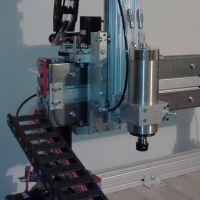
Why the '1-or-2' adapter you might be wondering.. Here's a picture of the stock hot end adapter with two extruders.
I had no luck finding a configuration that didn't touch. The spacing just seems wrong for more than one extruder. Maybe I was missing something? But it was easy to CAD up a replacement:
Things I have noticed so far with the two extruder experiments:
- The RAMBO board gets extremely warm with everything powered (including the dedicated bed PS). That along with the Texas summer heat convinced me to add a small fan to push some air across it.
- Ext2 won't function on it's own. Ext1 has to be heated/ing for it to heat/etc.
- The repetier firmware Ext offsets make things easy on the slicing program.
- Using colors to specify the Ext in a print would be really nice; of course everything in the work flow would need to support that.
- Early on something in the machine was freezing up; I suspect maybe this was heat related. I did review the 2560 datasheet and selected a baud rate that seemed more reasonable since I remember some folks had issues with error rates. So it's that or the added fan that seems to have resolved the issue (at least for now).
- Long term, I will need to sacrifice some Z height to avoid risking the platform plastic to heat. Although, I probably won't hit 260C on purpose, it seems wise to not expose it to extended temperatures.
If there's interest, I'll update the 2xExtruder progress and add some more print result pictures.
- SeeMeCNC's decision to stop selling the acrylic kit: as a owner of said kit, good decision. If I could do it over again, I would have gone with the wood version.
- EZStruder: I had Steve's Extruder working and was not terribly unhappy with it. But, this was a nice upgrade - the reduced noise alone is worth the price and retraction seems much better behaved.
- I still think the big issue that doesn't yet appear to be addressed is the sanding of the injected molded parts to fit the universal joints so they move "smoothly". There's too much left to error there and with all the various arms I see folks have made, it seems to speak loudly for the need to change it.
But, what have I been doing (besides working way too much)...
Early on in the two-extruder setup I managed to melt some of the liner in one hot-end. Did you know you can actually break a push-to-fit pneumatic fitting with the EZStruder?
Turns out with enough kapton tape and heat-shrink tubing, you can hold the guide tube in a broken push-to-fit fitting if you do manage to break it. It will hopefully last until the replacement and spares show up.
And at some point I need to CAD up an adapter for these E3D hot ends so I can stop worrying about melting liners:
The Traxxis rod ends have really nice movement though and can easily be positioned with a couple of nuts (~$7 for 12 rod ends). I can see why they are popular in the DIY Rostock Reprap crowd.
- The RAMBO board gets extremely warm with everything powered (including the dedicated bed PS). That along with the Texas summer heat convinced me to add a small fan to push some air across it.
- Ext2 won't function on it's own. Ext1 has to be heated/ing for it to heat/etc.
- The repetier firmware Ext offsets make things easy on the slicing program.
- Using colors to specify the Ext in a print would be really nice; of course everything in the work flow would need to support that.
- Early on something in the machine was freezing up; I suspect maybe this was heat related. I did review the 2560 datasheet and selected a baud rate that seemed more reasonable since I remember some folks had issues with error rates. So it's that or the added fan that seems to have resolved the issue (at least for now).
- Long term, I will need to sacrifice some Z height to avoid risking the platform plastic to heat. Although, I probably won't hit 260C on purpose, it seems wise to not expose it to extended temperatures.
If there's interest, I'll update the 2xExtruder progress and add some more print result pictures.
Re: dmlonestar - Rostock build
I think this the first post i've seen with some someone actually printing with dual hot ends. so I'm hoping you continue working on it and get it dialed in.
I would like too see how you end up mounting the 2 ed3 hot ends, those heat sinks are big and take up a lot of room, would probably have to mount it underneath the platform. maybe...
I would like too see how you end up mounting the 2 ed3 hot ends, those heat sinks are big and take up a lot of room, would probably have to mount it underneath the platform. maybe...
My rostock build log http://forum.seemecnc.com/viewtopic.php?f=42&t=1228
Re: dmlonestar - Rostock build
Geesh, I was going to say that "Holy Crap! We've got lurkers who build 3D printers in their sleep! They do dual extruders without telling anyone, build units in about four hours, do test prints without posting a gosh darn thing to this forum and in their spare time, they extrude used tires into bullet-proof filament."cambo3d wrote:I think this the first post i've seen with some someone actually printing with dual hot ends. so I'm hoping you continue working on it and get it dialed in.
I would like too see how you end up mounting the 2 ed3 hot ends, those heat sinks are big and take up a lot of room, would probably have to mount it underneath the platform. maybe...
Wow. Thanks for the post.
Technologist, Maker, Willing to question conventional logic
http://dropc.am/p/KhiI1a
http://dropc.am/p/KhiI1a
-
Eaglezsoar

- ULTIMATE 3D JEDI
- Posts: 7159
- Joined: Sun Apr 01, 2012 5:26 pm
Re: dmlonestar - Rostock build
dmlonestar, what was the traxxas part number for the rod ends that you used?
“ Do Not Regret Growing Older. It is a Privilege Denied to Many. ”
-
nathanstenzel
- Printmaster!
- Posts: 82
- Joined: Thu Jul 11, 2013 1:11 pm
Re: dmlonestar - Rostock build
So.....what was the traxxas rod end part number?