
Hey All!
Here's my build log along with notes for anyone that may be building the R7 version of the model. My printer arrived Monday, almost exactly 330 hours after ordering it. Needless to say I took off Tuesday from work so I could spend most of the day building the printer!
Note, I am maintaining a series of high resolution shots on a flickr set here. Thanks to Eye-Fi, adding pictures to the set is a breeze. I'll try to update the set as often as possible (proably more often than this build log) - http://www.flickr.com/photos/75376147@N ... 976583770/
[img]http://farm9.staticflickr.com/8521/8550 ... c3b45d.jpg[/img]
[img]http://farm9.staticflickr.com/8531/8553 ... 901f6b.jpg[/img]
(had to make this meme, I felt it as appropriate)
Note2: I am referencing Version 1.13 of Geneb's amazing 125 page manual as my primary build guide. Beyond this, I'm using Mhackey's great build log. And lastly, when stuck/confused about something (like threading the supports near the power supply), I reference the SeeMeCNC youtube videos. So far, these 3 sources have provided great insight into how to build this printer.
Cassetti's black Rostock MAX build
Cassetti's black Rostock MAX build
(No trees were killed to post this message, but a large number of electrons were terribly inconvenienced.)
Re: Cassetti's black Rostock MAX build
Current build progress:
Yesterday I assembled the base and installed the top, secured the 3 motors and 9 pulleys in the base.
[img]http://farm9.staticflickr.com/8382/8552 ... b119c6.jpg[/img]
Build notes (from memory since I'm working)
[*] vice grips / hemostat works WONDERS for pushing the locking nuts into panels
[*]Mhackney's build provides awesome list of part numbers for hunting down panels (I remove as needed, didn't remove tape all at 1 time)
[*]Really wish the nuts/bolts had labels - I hate SAE - how do I know what a 6-32 looks like compared to a 10-32??
[*]Don't know why people complain about removing the tape from panels - isn't any harder than removing application tape from a vinyl decal - peal slow and most of the tape even around text comes off with no issue!
[*]Installing heating resistor cores into the hotend was a PITA, I found clamping the resistor into a hemostat and clamping the hemostat to my desk mounted vice helped wrap the aluminum foil TIGHT
[*] Installing the motors AFTER installing the top cover is VERY tight fit for the 2 screws near the doors, suggest installing motors and pulleys prior to installing the top base
[*]The section in Geneb's pdf about threading those two cover supports near the power supply needs a few updates - 1, it doesn't say where to find a 10-32 screw in the set (in the youtube video part 2 assembly by seemecnc, I discovered there is one in the extruder kit, which saved me a $30 trip to sears for a tap set!) . And secondly, there is no clear indication of where the 2 supports go - again I had to review the youtube video to know where they went.
[*]Following Geneb's suggestion to tighten down 1 part of the top base panel first and then tighten the rest worked pretty well - though I noticed as tightening that my base started to crack (under the black melamine top) and noticed 2 pair of supports were not properly seated, soon as I nudged the tri-support panels into place everything snapped together nicely
[*]Is the included wrap around cover for the base really white?? I have a black wood kit, shouldn't the wrap around base be black? Looks like I'll need to spraypaint or use my vinyl printer at work to make up some cool graphics for it....
I'm sure I'm missing something, but those are my notes from my first full day building the printer
edit: just remembered another tip:
[*] The instructions for installing the heated bed (both sets) describe installing the t-nuts, but it doesn't clarify where to place the t-nuts. While you would expect them to be installed on the bottom side of the top base, it doesn't show any pictures or explain this. Since the included screws to mount the Onyx bed are very short, I had to test the mounting the whole assembly with one t-nut installed on the bottom to make sure they would reach! Since they are t-nuts, they could just as easily have been installed on the top of the plate (hence the confusion).
Last edited by cassetti on Wed Mar 13, 2013 1:43 pm, edited 1 time in total.
(No trees were killed to post this message, but a large number of electrons were terribly inconvenienced.)
-
Eaglezsoar

- ULTIMATE 3D JEDI
- Posts: 7159
- Joined: Sun Apr 01, 2012 5:26 pm
Re: Cassetti's black Rostock MAX build
I can't believe the wrap around cover is white. I was going to order the black set, I'm glad i didn't. You should not have too paint anything but that white sure will stand out.
Your graphic idea would really look cool, if you displace most of the white color. Hopefully Gene will be reading this and will modify the docs with your suggestions.
Your graphic idea would really look cool, if you displace most of the white color. Hopefully Gene will be reading this and will modify the docs with your suggestions.
Re: Cassetti's black Rostock MAX build
The black is REALLY a nice look, don't let the wrap around deter you. It looks like it could probably be painted with spraypaint no problem. Fortunately I have a 36" wide format Roland printer/plotter at work I can use to cut some graphics. I might do a negative graphic which I cover the entire panel in black, and remove the graphic parts to expose the white.Eaglezsoar wrote:I can't believe the wrap around cover is white. I was going to order the black set, I'm glad i didn't. You should not have too paint anything but that white sure will stand out.
Your graphic idea would really look cool, if you displace most of the white color. Hopefully Gene will be reading this and will modify the docs with your suggestions.
Any ideas what sort of graphic to put? The SeeMeCNC eye's are a bit too cheesy for me.
(No trees were killed to post this message, but a large number of electrons were terribly inconvenienced.)
-
Eaglezsoar
- ULTIMATE 3D JEDI
- Posts: 7159
- Joined: Sun Apr 01, 2012 5:26 pm
Re: Cassetti's black Rostock MAX build
Do you remember the pictures that had a Rostock with the yellow bumblebee, I thought that really looked cool.
Just an idea.
Just an idea.
Re: Cassetti's black Rostock MAX build
Yeah, i was halfway dissapointed when i didn't see it on the top plate of my printer.Eaglezsoar wrote:Do you remember the pictures that had a Rostock with the yellow bumblebee, I thought that really looked cool.
Just an idea.
(No trees were killed to post this message, but a large number of electrons were terribly inconvenienced.)
Re: Cassetti's black Rostock MAX build
Almost second-guessed the placement of my idlers in the base because the pictures are misleading - when taken from above, it looks like the two are parallel, when in reality the rear one is mounted higher up.
Here's a different angle shot of the idlers
[img]http://farm9.staticflickr.com/8374/8554 ... 65c5_z.jpg[/img]
Here's a different angle shot of the idlers
[img]http://farm9.staticflickr.com/8374/8554 ... 65c5_z.jpg[/img]
(No trees were killed to post this message, but a large number of electrons were terribly inconvenienced.)
Re: Cassetti's black Rostock MAX build
[img]http://farm9.staticflickr.com/8371/8555 ... 1113ee.jpg[/img]
Got another 3 hours last night to play with the Rostock.
Few notes:
[*] Installing the Rambo inside the door was pretty easy. I suggest using metal washers for pulling in the T-Nuts. I used the plastic washers and the flex of the plastic pushed the t-nut partially out when I was removing it (started to loosen the nut, then went upstairs to greet my wife) - had to remove the t-nut, rotate the teeth to another fresh area of wood, and re-install.
[*] Geneb's instructions for section 7 mention to use a #4-40 x ¾ socket cap screw. Only I had NONE of these in my kit! I ended up using some other screws I had for this part of the install
[*] Had to buy a new set of longer Allen wrenches at sears last night to reach the T-slot screws. But it seems that none of the SAE or Metric properly fit the screws! I was using a 9/64th, but after installing the rails, I either stripped the screw heads, or I stripped my Allen wrench. All I know is getting out those rails out will take patience (and a new set of ball-socket allen wrenches!)
[*] At section 12 - adjusting the top support plate - try as I might (even loosening the base of the rail) I could NOT get the rail flat against the inside surface of the t-slot rail material..... Though it seems all 3 rails have the same gap between the rail and the inside surface of the t-slot..... The manual says this is a big deal, but I can't get it flush....
[*] Section 13 - Figure 39 threw me off, I didn't know what parts I was looking for, took me a few times to realize there are 2 filament spool brackets AND two extruder brackets (the way it's worded threw me off for 5 minutes)
[*] One of my 3 Extruder support spacers had a cracked piece around one of the locking nut spaces. Few dabs of wood glue, and clamped it over night, should be ready for assembly tonight
[*] I don't know if it's just me, but the red text in Geneb's pictures is HORRIBLE. Half the time I look at the pictures and don't even realize there's text on the picture unless I get 2 inches away from the screen/printout. Maybe something more visible like white text would help... (@Geneb - if you need me to photoshop some text onto some photos, let me know, I'd be more than happy to help)
Thankfully it appears the "frame" is complete. All I need is to build the extruder, carriage, cheapskate assemblies, install belts, and wire this baby up! Hopefully I'll have plastic flowing by the weekend! If it weren't for my pesky work, I'd probably almost be finished by now!
(No trees were killed to post this message, but a large number of electrons were terribly inconvenienced.)
Re: Cassetti's black Rostock MAX build
Which pictures?
BTW, if you guys want I can upload the whole figure set. It's around 19MB (169 files) worth of images. The filenames match the figures in the guide.
g.
BTW, if you guys want I can upload the whole figure set. It's around 19MB (169 files) worth of images. The filenames match the figures in the guide.
g.
Delta Power!
Defeat the Cartesian Agenda!
http://www.f15sim.com - 80-0007, The only one of its kind.
http://geneb.simpits.org - Technical and Simulator Projects
Defeat the Cartesian Agenda!
http://www.f15sim.com - 80-0007, The only one of its kind.
http://geneb.simpits.org - Technical and Simulator Projects
Re: Cassetti's black Rostock MAX build
(first off no disrespect, you've done a fantastic job with the manual, I'm VERY grateful, when I built my prusa i2 "ecksbot" I had only a handful of forum thread posts with crappy pictures from the vendor on how to build it - boy was that a disaster!)geneb wrote:Which pictures?
BTW, if you guys want I can upload the whole figure set. It's around 19MB (169 files) worth of images. The filenames match the figures in the guide.
g.
I'll just label a few pictures that are difficult to read with the red text for me. (Note, 15+ years ago I was diagnosed with a very mild form of color blindness, but I really can't pinpoint which colors I have trouble with, but I suspect that's why it's hard for me to read this red text). Figure 26, Figure 30, Figure 34 (half the text is in the background which makes it hard to read 'mounting'), Figure 40 - those are the ones I've seen so far. One thing I do when putting text on a photo for my work's marketing material, is usually to use a bright colored text like white, and then add a thin black outline (easily done in photoshop). For whatever reason, adding a thin black outline around white text really makes it pop against pretty much any background.
Like I said, not a big deal, but for whatever reason - that red text is hard as hell for me to read, I don't need the high res shots, pretty much past most of those steps
(No trees were killed to post this message, but a large number of electrons were terribly inconvenienced.)
Re: Cassetti's black Rostock MAX build
I used Paint.NET to do the annotation and I don't think it offers the text outline feature. I can certainly see your point on the figures you listed. White would have been a better choice.
g.
g.
Delta Power!
Defeat the Cartesian Agenda!
http://www.f15sim.com - 80-0007, The only one of its kind.
http://geneb.simpits.org - Technical and Simulator Projects
Defeat the Cartesian Agenda!
http://www.f15sim.com - 80-0007, The only one of its kind.
http://geneb.simpits.org - Technical and Simulator Projects
Re: Cassetti's black Rostock MAX build
cassetti wrote:[img]http://farm9.staticflickr.com/8371/8555 ... 1113ee.jpg[/img]
Got another 3 hours last night to play with the Rostock.
Few notes:
[*] Installing the Rambo inside the door was pretty easy. I suggest using metal washers for pulling in the T-Nuts. I used the plastic washers and the flex of the plastic pushed the t-nut partially out when I was removing it (started to loosen the nut, then went upstairs to greet my wife) - had to remove the t-nut, rotate the teeth to another fresh area of wood, and re-install.
[*] Geneb's instructions for section 7 mention to use a #4-40 x ¾ socket cap screw. Only I had NONE of these in my kit! I ended up using some other screws I had for this part of the install
[*] Had to buy a new set of longer Allen wrenches at sears last night to reach the T-slot screws. But it seems that none of the SAE or Metric properly fit the screws! I was using a 9/64th, but after installing the rails, I either stripped the screw heads, or I stripped my Allen wrench. All I know is getting out those rails out will take patience (and a new set of ball-socket allen wrenches!)
[*] At section 12 - adjusting the top support plate - try as I might (even loosening the base of the rail) I could NOT get the rail flat against the inside surface of the t-slot rail material..... Though it seems all 3 rails have the same gap between the rail and the inside surface of the t-slot..... The manual says this is a big deal, but I can't get it flush....
[*] Section 13 - Figure 39 threw me off, I didn't know what parts I was looking for, took me a few times to realize there are 2 filament spool brackets AND two extruder brackets (the way it's worded threw me off for 5 minutes)
[*] One of my 3 Extruder support spacers had a cracked piece around one of the locking nut spaces. Few dabs of wood glue, and clamped it over night, should be ready for assembly tonight
[*] I don't know if it's just me, but the red text in Geneb's pictures is HORRIBLE. Half the time I look at the pictures and don't even realize there's text on the picture unless I get 2 inches away from the screen/printout. Maybe something more visible like white text would help... (@Geneb - if you need me to photoshop some text onto some photos, let me know, I'd be more than happy to help)
Thankfully it appears the "frame" is complete. All I need is to build the extruder, carriage, cheapskate assemblies, install belts, and wire this baby up! Hopefully I'll have plastic flowing by the weekend! If it weren't for my pesky work, I'd probably almost be finished by now!
I stopped following along in gene's manual, but that's just me I like to have some sort of sequence to it, I didn't like the way it was written but it helped in certain areas. Its better than nothing Seemecnc needs to go over it, fix the errors as they come out with updates.
My rostock build log http://forum.seemecnc.com/viewtopic.php?f=42&t=1228
Re: Cassetti's black Rostock MAX build
That's the thing, I'm guessing the printer is evolving too fast. I mean now I hear they are working on an electronics kit that will require no crimping or extending wires! that will be AWESOME. I think really right now it would be pointless for SeeMeCNC to make an 'official' manual. I mean shoot, my printer is apparently R7, didn't they release this less than 3 or 4 months ago??
I personally found Gene's manual extremely helpful, screw sequence, as long as I end up with a 3D printer after I'm finished, I'm happy!
I personally found Gene's manual extremely helpful, screw sequence, as long as I end up with a 3D printer after I'm finished, I'm happy!
(No trees were killed to post this message, but a large number of electrons were terribly inconvenienced.)
Re: Cassetti's black Rostock MAX build
[img]http://farm9.staticflickr.com/8230/8559 ... 6b2247.jpg[/img]
Didn't get to accomplish much last night since it was a holiday and all (man that steak was delicious... lol).
Did attempt on starting the extruder assembly however I can't get past the first step! Those damn bearings just won't fit into the gear nicely, it keeps cocking to the side. I'm really afraid to mess up the bearing. I've even tried pulling it into place with a bolt and some washers, but it won't sit flat..... any advice on how I can install the bearings? Should I try sanding the inside slightly? I tried installing the bearing on both gears with no success.
(No trees were killed to post this message, but a large number of electrons were terribly inconvenienced.)
-
MorbidSlowBurn

- Printmaster!
- Posts: 169
- Joined: Sun Mar 03, 2013 5:33 pm
Re: Cassetti's black Rostock MAX build
I was cautious of the bearing install also. It seemed like too much force for my liking. But once started they went right in. My method was to use a bench top vice and the largest socket that fit on the bearing but not larger than the brearing diameter (you really want to put pressure on the outer bearing diameter as you can damage the bearing if you apply pressure on the face). I also used a piece of wood to protect the gear from the metal jaw of the vice. When in the vice the order was vice-wood-gear-bearing-socket-vice. I then tightened down the vice to press the bearing into place. To line the bearing up, take your time and make sure the bearing is over the hole in the gear.
Remembered when fully installed the bearing should be recessed slightly into the gear otherwise you will have problems with rubbing after assembly. There is a slight lip on the one side of the gear and that is the stop for installing the bearing. I believe the YouTube build video shows how to do this if I wasn't clear.
Edit: forgot the socket in the order between bearing and vice.
Last edited by MorbidSlowBurn on Fri Mar 15, 2013 11:19 am, edited 1 time in total.
Re: Cassetti's black Rostock MAX build
Thanks! I'll give that a shot and see how it goes - I'm still worried about getting it seated properly before I completely install. Is it ok if one side goes in before the other (IE, if i keep tightening, will it straighten out?)
(No trees were killed to post this message, but a large number of electrons were terribly inconvenienced.)
-
MorbidSlowBurn
- Printmaster!
- Posts: 169
- Joined: Sun Mar 03, 2013 5:33 pm
Re: Cassetti's black Rostock MAX build
If you use a large socket and vice it should go in fairly straight. Just put enough pressure to line everything up before applying force. Just remember the socket needs to push on the edge of the outer diameter of the bearing.
Re: Cassetti's black Rostock MAX build
Awesome, I'll give that a shot after work. The manual mentioned an 11mm socket, which I found also fit just perfectly into the gear itself without the bearing.MorbidSlowBurn wrote:If you use a large socket and vice it should go in fairly straight. Just put enough pressure to line everything up before applying force. Just remember the socket needs to push on the edge of the outer diameter of the bearing.
(No trees were killed to post this message, but a large number of electrons were terribly inconvenienced.)
Re: Cassetti's black Rostock MAX build
This method worked perfect. Though I was having a hard time holding everything while tightening the vice, so I used a pair of square "curiously strong magnets" (neodymium) to hold the bearing to the socket. Ok, step 1 done, what's nextMorbidSlowBurn wrote:If you use a large socket and vice it should go in fairly straight. Just put enough pressure to line everything up before applying force. Just remember the socket needs to push on the edge of the outer diameter of the bearing.
[img]http://farm9.staticflickr.com/8370/8560 ... 981b4d.jpg[/img]
(No trees were killed to post this message, but a large number of electrons were terribly inconvenienced.)

Re: Cassetti's black Rostock MAX build
If you have a drill press, that works well too. Using the largest diameter socket that will fit loosely into the bearing recess, and a socket extension, put the extension in the chuck, and use the drill press like an arbor press. Smooth, straight, well controlled bearing installation.
- dan
- dan
Re: Cassetti's black Rostock MAX build
[img]http://farm9.staticflickr.com/8366/8562 ... 66c122.jpg[/img]
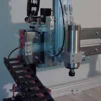
Haven't gotten too much farther yet.... now I'm stuck trying to figure out how to get these gears mated in the extruder. I'm at the 23 minute mark in the youtube video (part 4 -extruder assembly) where he says 'drop the idler into place' - does anyone have a higher def picture? I'm really confused - the film makes it hard to see exactly where the washers should be lined up and such. Or is there a better youtube video on the assembly of the extruder?
Haven't gotten too much farther yet.... now I'm stuck trying to figure out how to get these gears mated in the extruder. I'm at the 23 minute mark in the youtube video (part 4 -extruder assembly) where he says 'drop the idler into place' - does anyone have a higher def picture? I'm really confused - the film makes it hard to see exactly where the washers should be lined up and such. Or is there a better youtube video on the assembly of the extruder?
(No trees were killed to post this message, but a large number of electrons were terribly inconvenienced.)
-
MorbidSlowBurn
- Printmaster!
- Posts: 169
- Joined: Sun Mar 03, 2013 5:33 pm
Re: Cassetti's black Rostock MAX build
You have them positioned relatively correct. The two tabs on the idler slip into the holes of the base. All washers and o-rings are between the head of the screw and the plastic piece with the two notches. There was little nubs on the notched plastic piece that help to keep the washers in place.
Re: Cassetti's black Rostock MAX build
Ahh, I see now, that's how it holds the gears snug together. Thanks, I wasn't positive I had my nubs on the correct sideMorbidSlowBurn wrote:You have them positioned relatively correct. The two tabs on the idler slip into the holes of the base. All washers and o-rings are between the head of the screw and the plastic piece with the two notches. There was little nubs on the notched plastic piece that help to keep the washers in place.
(No trees were killed to post this message, but a large number of electrons were terribly inconvenienced.)
Re: Cassetti's black Rostock MAX build
Looking good so far, I wanted a rostock but I have no money and I still can't figure out how the delta's even work XD
Re: Cassetti's black Rostock MAX build
Yeah, I had to wait for my tax refund to afford mine - needless to say the day my federal refund was deposited into my bank account, was the day I ordered my Rostock. Delta printers are sexy, but I still think they need some more development time, the original design for the rostock was only released last August!tom10122 wrote:Looking good so far, I wanted a rostock but I have no money and I still can't figure out how the delta's even work XD
(No trees were killed to post this message, but a large number of electrons were terribly inconvenienced.)