Hey thought I'd post this I just found this uploaded minutes ago on Thingiverse.
I just printed one and looks like perfect fit for the belts. As simple as possible workable mod for keeping the belts in line on the idler bearings!! ...as long as it doesn't slip with use.
Very fast print, .2mm layer height turned out perfect.
Can't wait to put them on and test I'll post update on how it works later, might not have time today to do that though.
http://www.thingiverse.com/thing:91510
608 Bearing Flange for idler bearings!
-
truenorthtrader

- Printmaster!
- Posts: 148
- Joined: Sun Jan 13, 2013 8:09 pm
608 Bearing Flange for idler bearings!
- Attachments
-
-
Re: 608 Bearing Flange for idler bearings!
doesn't the rostock belts follow the center of the extrusion.
My rostock build log http://forum.seemecnc.com/viewtopic.php?f=42&t=1228
-
Jimustanguitar

- ULTIMATE 3D JEDI
- Posts: 2608
- Joined: Sun Mar 31, 2013 1:35 am
- Location: Notre Dame area
- Contact:
Re: 608 Bearing Flange for idler bearings!
You mean the extruded aluminum? Yes.cambo3d wrote:doesn't the rostock belts follow the center of the extrusion.
If the idler bearings are canted, the motor pulley is to one side or the other, or if the belt is curved/stretched, the belt can rub on the sharp cut edge of the aluminum extrusion. If you have a Rostock that isn't black, you may notice little black bits of stuff accumulating below the motor pulley. It's little chunks of the belt that are being filed off of the belt as it rubs on the sharp edge...
Awesome find, I'm going to have to print some of these!
Re: 608 Bearing Flange for idler bearings!
Jimustanguitar wrote:You mean the extruded aluminum? Yes.cambo3d wrote:doesn't the rostock belts follow the center of the extrusion.
If the idler bearings are canted, the motor pulley is to one side or the other, or if the belt is curved/stretched, the belt can rub on the sharp cut edge of the aluminum extrusion. If you have a Rostock that isn't black, you may notice little black bits of stuff accumulating below the motor pulley. It's little chunks of the belt that are being filed off of the belt as it rubs on the sharp edge...
Awesome find, I'm going to have to print some of these!
you missed my point here, that photo shows the belt not in the center of the extrusion. making me think how does he have his belt routed.
My rostock build log http://forum.seemecnc.com/viewtopic.php?f=42&t=1228
-
truenorthtrader
- Printmaster!
- Posts: 148
- Joined: Sun Jan 13, 2013 8:09 pm
Re: 608 Bearing Flange for idler bearings!
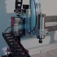
Hey I didn't install them yet I just put it against the belt on the tower to show it fits the width of the belt.
They snap around the 608 bearing, 1 on each side keeping the belt centered.
This has been a problem I never solved although I got the belts pretty close to center it's not prefect. I had an idea of making this exact thing but didn't get around to it...but this person did it so less work for me!
I'll likely install then in the next few days and update how they work.
-
Jimustanguitar
- ULTIMATE 3D JEDI
- Posts: 2608
- Joined: Sun Mar 31, 2013 1:35 am
- Location: Notre Dame area
- Contact:
Re: 608 Bearing Flange for idler bearings!
cambo3d wrote:Jimustanguitar wrote:You mean the extruded aluminum? Yes.cambo3d wrote:doesn't the rostock belts follow the center of the extrusion.
If the idler bearings are canted, the motor pulley is to one side or the other, or if the belt is curved/stretched, the belt can rub on the sharp cut edge of the aluminum extrusion. If you have a Rostock that isn't black, you may notice little black bits of stuff accumulating below the motor pulley. It's little chunks of the belt that are being filed off of the belt as it rubs on the sharp edge...
Awesome find, I'm going to have to print some of these!
you missed my point here, that photo shows the belt not in the center of the extrusion. making me think how does he have his belt routed.
Gotcha.

Re: 608 Bearing Flange for idler bearings!
Is there an update on these? I have been a little concerned about the sharp corner on the extrusion. I think misalignment on a belt could rub there and cause trouble? I went back and used a rubber bullet in my dremel to polish the corners (I could reach) a little. I can't get to the inner/bottom without a major disassembly. If these work I'll print some on my Printrbot jr.
-"Simpler is better, except when complicated looks really cool."
-"As soon as you make something fool proof...along comes an idiot."
-"I have not failed. I've just found 10,000 ways that won't work." ~Thomas Edison
-"As soon as you make something fool proof...along comes an idiot."
-"I have not failed. I've just found 10,000 ways that won't work." ~Thomas Edison
-
truenorthtrader
- Printmaster!
- Posts: 148
- Joined: Sun Jan 13, 2013 8:09 pm
Re: 608 Bearing Flange for idler bearings!
Hey I tried putting one on today.
Various Problems with it once assembled...looked good on bearings but not useable.
I haven' t put the bearing back on to print more but I adjusted the file making necessary changes (but I would suggest just trying what I did below).
http://www.thingiverse.com/thing:93047
I just put it back together and actually got it perfectly straight without any modifications.
This time I tightened enough so the bearing assembly wouldn't SLIP, but stay still, then TAPPED the screw on the side I wanted to lower slightly a bit at a time until straight, THEN I tightened fully.
It was pretty easy this way and didn't need another person or mods so I'm keeping it as designed.